It looks like you're using an Ad Blocker.
Please white-list or disable AboveTopSecret.com in your ad-blocking tool.
Thank you.
Some features of ATS will be disabled while you continue to use an ad-blocker.

Free Energy Using Synthetic Tornadoes
page: 3share:
I have now fabricated and stacked over 600 PTP’s. I still have not exceeded the 10 in/sec air flow threshold. But, even though I have to use my
hands to feel the air, it is now more than ever obvious that there is perpetual air flow, and the amount to air is an exponential function of PTP
stack size.
On July 21 I took the PTP stack I had at the time and showed it to a local company that does plastic extrusions. I attempted to convince them to develop the tooling necessary to extrude a PTP stack of arbitrary size. I explained to them that these stack tubes if long enough would perpetually pump enough air to do real useful work. They could sell these tubes to a third party who would produce and market free energy producing devices. Several days later after giving them requested drawings and other information I received a email stating that, at that this time they lack the resources necessary to fund this project.
This is most unfortunate for all of us. Because, If they had proceeded back in July, We would be seeing preliminary free energy producing ST devices coming to market today.
On September 27 when I had a stack of over 400 PTP’s, I Emailed them offering to drive down and show it to them. I have yet to receive a response.
Currently I am fabricating more PTP’s to add to the stack.
Has anyone else out there been experimenting with a PTP stack?
please the jet streams (theres more then one) are not i repet not prepectial motoin . 1 the earths rotation has a dirrect involvment in the amount of
energy Used buy the jet stream 2 the suns light wich translates into heat also imparts energy into the jet streams .
I hate to be the barer of bad news but what hes describes CANOT work the way he clames. once your air has entered the holes theres NO way to natrial get it to enter on hole in preference to another Unless your imparting energy someware in this design .
heres a fun exparment to do with your kids to show whats hes claming is free energy .
eather get a big 100 gALLON FISH TANK OR MAKE A GLASS BOX (it doesent have to hold water.
now in one end put a samm pile of semi wet leaves mixed with torn paper and mabby just a little wood trown in (say a 4 ince round high pile will do .
at the other end (o box is accutly fish tanked shaped Recktangeled is a better description ( but any good size will do )
anyway at the other end put ooo say ten ice cubes .
so now we have a fish tank say 3 feett high by 2 foot wide buy three feet long with ice at one end and the leaves paper wood mix pile at the othere let it sit for 15 minits (must be inside no other air currents to work well) then light the other end (burning the wet leaves paperwood mix and watch what happens next .
the leaves being wet will produce much smoke .
but during that 15 minit wate the air inside the tank got cooled buy the ice at the other end of the tank so now we have a fire heating the air with acold layer on TOP of a warm new RAPILDY expanding layer in a retangel box .
you have just craeted a frount the warm air being drawn to the cold air wanting to rise and if all goes well youl get a real real cool 2 foot talll TORNADO at the cold end (you can see it tahts why you made a smoke fire and not justa plan one ) a man made tornado its realy cool.
ps have done this it was a 9th grade science class experment my teacher showd us .
the point to all this its the difference in temp or the spin of a planet that creats motion in air . there no magice way to get stangent air to move WITHOUT out side energy being applyed. ty have a nice day
reply to post by xxcalbier
Your set up create the conditions for a tornado to form. A condition I call a hole in the atmosphere. I cover this in my paper I published here on ATS.
The Tornado and The Channelized Air Effect.
(www.abovetopsecret.com...)
I idea of publishing all the details necessary for making your own PTP stack here on ATS, Is so that a skeptic can fabricate it and do his own investigative inquire. Saying it won’t work and using that as an excuse for not investigating plays no part in the fundamentals of modern science.
(Note to moderators: Could you please move this thread back to the science and technology form where it belongs.)
I have just applied for a provisional patent on an ST design.
Application # 61526030 , Filing date 22-AUG-2011
Title: Midpoint Reversed Directionally Coupled Double Chamber Structure For The Natural Induction Of A Tornado.
This design is to good and to practical not to apply. Here is an excerpt from the application.
[atsimg]http://files.abovetopsecret.com/images/member/1d3ce84ed7e6.jpg[/atsimg]
[atsimg]http://files.abovetopsecret.com/images/member/ea5ca8c87f94.jpg[/atsimg]
[atsimg]http://files.abovetopsecret.com/images/member/8be2162f11b4.jpg[/atsimg]
Description Of Preferred Embodiments
Figures 1 and 2 show the structure of the ST. The end views shown in these figures are what one would see if one were to bend up the ends of the structure shown in the center drawings. Referring to figure 1, item 1 is one of the two chambers. Item 2 is a channel connecting the two chambers and is responsible for the directional coupling. Item 3 is the mid reversal point where the channel (item 2) is moved form the top of the structure to the bottom. This is shown with the hidden lines (item 2) in figure 2.
There are no dimensions shown in these figures (1 and 2) because they can very widely and the ST will work. As a starting point, the channel (item 2) thickness should be equal to 1/6 of the chamber (Item 1) diameter. This structure will most likely be very long and very thin and will be coiled up to make a compact unit. As can be seen, the structure is the same on either side of the reversal point (item 3). It is simply flipped over at the reversal point. The halves have the same cross section for their entire lengths which makes it easy to fabricate through extrusion. This extrude able material will be referred to as “Directionally Coupled Double Chamber” material or DCDC or DC^2 (pronounced DC squared). Although figures 1 and 2 shows the to halves butted together like this, they could also be connected by Ying out the ends and then connecting the Y’s together. The Ying process will be explained in the “Tips for experimenters” section.
Figure 3 shows the air flow pattern inside the ST structure. The flow consists of 2 helical flow tornadoes. One in each chamber. The air of each tornado is fed into the other to form a loop. This is known as a positive feed back loop.
The flow arrows (Item 3) show the longitudinal component of the helical flow it the upper chamber while item 4 shows the same for the lower chamber. The flow arrows (Item 8) show the rotational component of the helical flow it the upper chamber while item 9 shows the same for the lower chamber. Notice that the helical flows are the same on both sides of the reversal point (item 10). The flow arrows (Item 6), on one side of the reversal point (item 10), shows the air flow through the directionally coupling channel transferring air from the helical flow in the upper chamber to that in the lower chamber. The flow arrows (Item 7), on the other side of the reversal point (item 10), shows the air flow through the directionally coupling channel transferring air from the helical flow in the lower chamber to that in the upper chamber. The flow arrows in sequence from items 3 to 6 to 4 to 7 show the path of the positive feed back air flow loop.
Referring to the illustration on the left of figure 4, the air flow arrow (item 2) is in the same direction as the tangential velocities at the top of the rotational component flow arrows (items 1 and 3) in each chamber. Putting the coupling channel at the top with these air flows as shown here will result in the rotational components forcing air into the channel from one side and sucking it out from the other in the direction of flow arrow Item 2. This one way forced coupling is what is being referred to as directional coupling. The illustration on the right of figure 4 shows another example of directional coupling.
The descriptions in this document deal with two equal size round cross section chambers containing a helical flow tornado in each chamber. This is not the only configuration for an ST. The chambers could be just about any size or shape and still allow for helical flow tornadoes to exist. If a channel connecting these chambers is placed in the right spot then directional coupling will occur. There could be more that just two helical flow tornado containing chambers. As long as the helical air flow in the chambers combined with the air flow through directional couplings between these chambers results in a positive feed back air flow loop, The ST structure in question is covered by this patent.
Referring back figure 3, If the ends of the lower chamber and the ends of the coupling channels are plugged as shown with item 5, The helical flow tornado in the upper chamber will suck in air at the input (item 2) and blow it out the output (item 1). The ST is an air pump utilizing the same natural mechanism behind a real tornado.
Hi ATSers
I am bumping this thread by letting you know that I have (at great expense) applied for a non provisional patent. The application was filed May 9 2012. The application number is 13/467,836 and its projected publication date is 02/28/2013.
As of this date, although this design has been published in the previous post for over a year, no one has debunked the design by building it, test it, and notifying me of unsatisfactory results.
Cool.. glad you updated.. got a prototype even a small one hooked up to a small generator that can even light a LED that we can look at?
reply to post by JohnPhoenix
Below is a picture of the latest ST I built. The output is in the upper left hand corner and the input is at the lower center where the white piece of paper is. It was made by hand slitting 1/4 in. ID tubing and epoxying in a piece of plastic harvested from V weather striping. The little pieces of cardboard were used to maintain the channel gap.
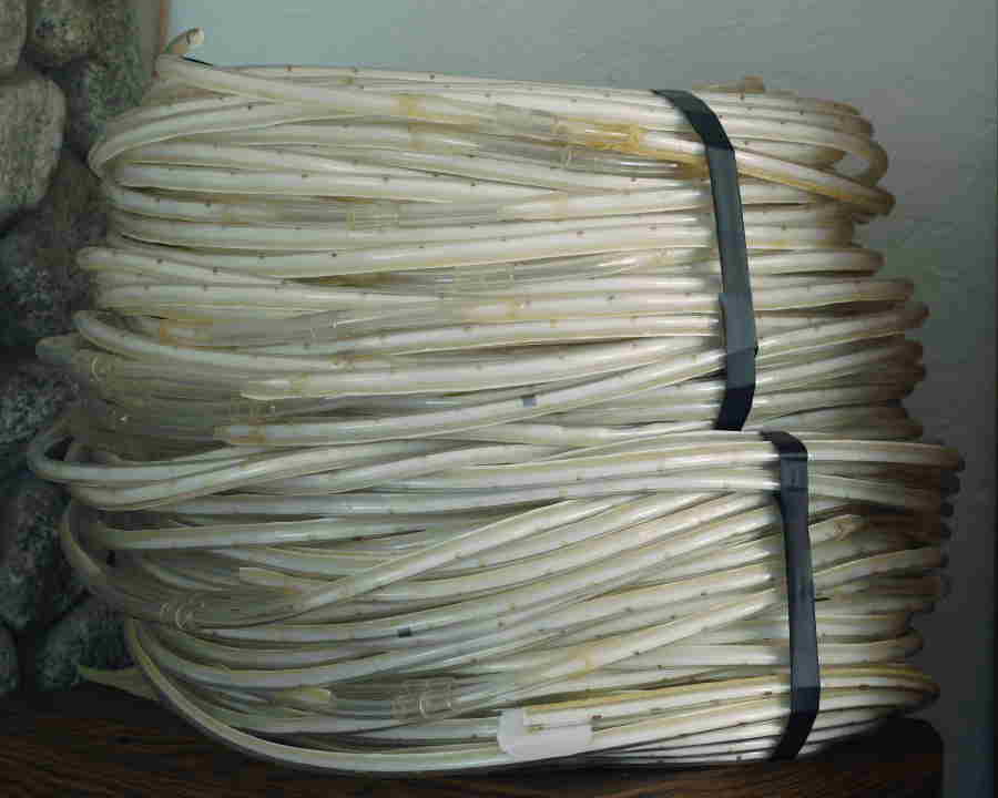
I am guessing that this unit pumps air with an output velocity of about 1 in./sec. It is enough air to easily feel but not enough the give any sort of visual demonstration.
I was able to come up with the following equation which gives an estimate of the output air velocity as a function of the chamber diameter and length.
V = (K2)(K1)^(L/d)
where,
V is the output velocity of airflow measured in in/sec,
K2 = 7.45 x 10^(-5) in/sec
K1 = 1.000112 in/sec
L = Length in inches
d =Diameter of the chambers in inches.
It is intended for this equation to be used by some one with resources who wants to verify/experiment with this ST technology. By Using this equation to select L and d for given desired output velocity, one would be assured to build one with an impressive performance.
I believe some organization has already done this. They just haven’t come forward yet because there are certain monetary advantages to waiting until one is ready.
Below is a picture of the latest ST I built. The output is in the upper left hand corner and the input is at the lower center where the white piece of paper is. It was made by hand slitting 1/4 in. ID tubing and epoxying in a piece of plastic harvested from V weather striping. The little pieces of cardboard were used to maintain the channel gap.
I am guessing that this unit pumps air with an output velocity of about 1 in./sec. It is enough air to easily feel but not enough the give any sort of visual demonstration.
I was able to come up with the following equation which gives an estimate of the output air velocity as a function of the chamber diameter and length.
V = (K2)(K1)^(L/d)
where,
V is the output velocity of airflow measured in in/sec,
K2 = 7.45 x 10^(-5) in/sec
K1 = 1.000112 in/sec
L = Length in inches
d =Diameter of the chambers in inches.
It is intended for this equation to be used by some one with resources who wants to verify/experiment with this ST technology. By Using this equation to select L and d for given desired output velocity, one would be assured to build one with an impressive performance.
I believe some organization has already done this. They just haven’t come forward yet because there are certain monetary advantages to waiting until one is ready.
Have you considered if you can get enough pressure using this with a tesla air turbine?
reply to post by hawkiye
To clarify, according to the above equation, (also known as equation 1) one can chose L and d to make an ST with sufficient output air velocity (V) and pressure (pressure is proportional to V^2) to drive any type of turbine at any power level desired.
The output air velocity of the ST I built is to small to over come the bearing friction of any real Tesla turbine. The problem is d, the chamber diameter, at 1/8 in. is to big. In order to get sufficient air flow the ST would be to big and take to long to build by hand.
The logical choice of action would be to have a large spool of DC squared material with a small diameter made through a custom extrusion process. The cost to have this done is way beyond my budget. This cost, however, is insignificant to the companies I contacted last year.
Most of these companies are auto companies. For them, the consequences of being wrong and ignoring the technology while their competitors didn’t would be catastrophic. For this reason I am positive most if not all of these auto companies have built and tested this ST design.
reply to post by graysquirrel
Why can't you just buy some tubing of the right size and wrap it? Why do you need to make special tubing? Home and hardware stores have rolls of tubing in all different sizes. Sometimes we over complicate things.
You should make a youtube video of how to make one of these. Most of us do not have the understanding to read your blueprints of this nor the time to invest to learn to understand it as you do. But I bet if I saw you make one I could make one. So If I am off base with my comments above that is probably why.
reply to post by hawkiye
Figure 4 of this post (www.abovetopsecret.com...) shows the cross section of the tubing needed. Hardware stores do not carry tubing like this. I had to make my own by slitting ordinary round tubing and inserting a piece of plastic to make 2 chambered tubing with a channel connecting them.
Figure 4 of this post (www.abovetopsecret.com...) shows the cross section of the tubing needed. Hardware stores do not carry tubing like this. I had to make my own by slitting ordinary round tubing and inserting a piece of plastic to make 2 chambered tubing with a channel connecting them.
It looks like you have coiled up tubing that exits a pressurized air flow.
Wouldn't this in some way depend on the earth's rotation?
Where else would the power for the airflow arise?
Tesla patented a one way air flow device of a gas diode.
Always patent its a great idea.
Wouldn't this in some way depend on the earth's rotation?
Where else would the power for the airflow arise?
Tesla patented a one way air flow device of a gas diode.
Always patent its a great idea.
reply to post by graysquirrel
I thought of
www.google.com...
and did a search for fan with no power but only this looked close.
I have no idea how it works but did feel the air from the cone shape.
Unless that is the secret.
ED:
en.wikipedia.org...
I thought of
www.google.com...
and did a search for fan with no power but only this looked close.
I have no idea how it works but did feel the air from the cone shape.
Unless that is the secret.
ED:
The fan works by drawing 27 litres of air per second[9] in through an inlet in the base pillar and forcing it through an outlet in the upper ring. The jet of air travels over the aerofoil shape of the ring, creating local low pressure, thereby pulling air from behind it as it decelerates in a process known as inducement, a property of Bernoulli's principle.
en.wikipedia.org...
edit on 10/21/2012 by TeslaandLyne because: (no reason given)
Well I salute the OP in part, as his design attempt is a breath of fresh air with all the skeptics, liars and disinformants on here.
However, like another pointed out, his design is very complicated on paper to the 3d / 4d mind.
Maybe it's my right-brained ways, but when I make a thing, I use very minimal design notes and instead concentrate on building the thing and fixing / improving it on the fly.
I struggle to understand where the source airflow comes from (does the OP blow into it and seal the thing up?) to self-perpetuate.
Also, for an upscaled model, would it not require an initial 'burst' of airflow from a compressed air-tank or something?
If he made a video, on youtube, of the various in's and out's this, that and the other etc, people would copy and innovate the idea, maybe, just maybe we'd see a breakthrough.
You gotta get details off the paper and the abstract and into the world of substance.
reply to post by TeslaandLyne
Sorry for the delayed response. As you can see, this thread can go dormant for long stretches at a time. I just don’t check it to often.
In the following excerpt from the provision patent I address the theory of operation. I hope this will answer some of your questions.
Sorry for the delayed response. As you can see, this thread can go dormant for long stretches at a time. I just don’t check it to often.
In the following excerpt from the provision patent I address the theory of operation. I hope this will answer some of your questions.
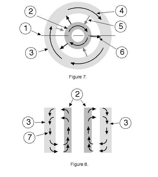
Theory of operation
Figure 7 shows the top view of a real atmospheric tornado. It consists of both an inner (Item 2) and outer (item 3) helical flow tornadoes. The rotational component of these tornadoes is shown by the item 4 arrows. Item 6 arrows shows the radial component of the spiral air flow transferring air form the upper inner tornado to the upper outer tornado. Item 5 arrows shows the radial component of the spiral air flow transferring air form the lower outer tornado to the lower inner tornado. Figure 8. shows the view of a slice of the tornado at the item 1 line in figure 7. Referring to figure 8, Item 2 shows the inner tornado with an upward helical flow and item 3 shows the outer tornado with a downward helical flow. The item 7 arrows shows the mushroom circulating air flow resulting in a positive feed back air flow loop.
It is assumed here that when atmospheric conditions create the mushroom air flow like Item 7 necessary for helical flows with a positive feed back air flow loop, then a tornado, both inner and outer parts, will naturally occur. The reason why a tornado form is not going to be covered here. Because the ST structure also creates the conditions for helical flows with a positive feed back air flow loop (see Description), a tornado will also naturally occur. For an ST the two helical flow tornadoes are side by side each in it own chamber.
Originally posted by WatchRider
You gotta get details off the paper and the abstract and into the world of substance.
No offense but the apparatus shown in the picture in this post (www.abovetopsecret.com...) is in the real world.
I would like to draw your attention to an article in the journal Nature. Here is the link.
www.nature.com...
To summarize, a researcher created and placed a very large number of self rolling balls on a race track. According to the second law to thermal dynamics such arrangement would result in a very large number of randomly moving self rolling balls. However, it was observed that, the balls alined then selves and traveled as an organized group around the race track.
This is experimental prove of the channelized air effect (CAE) as described in this thread. The self rolling balls are replaced by perpetually moving air molecules. Because CAE is the fundamental principal behind the ST or synthetic tornado (and natural tornados), this also proves that the ST as described in this thread can work.
a reply to: graysquirrel
Squirrel,
Your device is basically ideal for some of desktop fabrication technologies starting to get going in the open source world. Give me a shout some time.
Squirrel,
Your device is basically ideal for some of desktop fabrication technologies starting to get going in the open source world. Give me a shout some time.
new topics
-
German city in chaos as 'extremist' march sees calls for 'caliphate' and ISIS-style flags
Mainstream News: 1 hours ago -
College protesters want amnesty.
US Political Madness: 2 hours ago -
Shocking moment four men 'try to force Jewish pedestrian into car boot' in North London
Breaking Alternative News: 6 hours ago -
The 'Censorship-Industrial Complex'. It is coming to a nation state near you, any time now...
New World Order: 6 hours ago -
BREAKING: Astrazeneca admits for the first time its vaccine can cause deaths and serious injuries
Medical Issues & Conspiracies: 10 hours ago
top topics
-
New Bombshell Evidence Strongly Suggests Trump was Set Up in Classified Docs Saga
US Political Madness: 15 hours ago, 36 flags -
BREAKING: Astrazeneca admits for the first time its vaccine can cause deaths and serious injuries
Medical Issues & Conspiracies: 10 hours ago, 14 flags -
Shocking moment four men 'try to force Jewish pedestrian into car boot' in North London
Breaking Alternative News: 6 hours ago, 10 flags -
German city in chaos as 'extremist' march sees calls for 'caliphate' and ISIS-style flags
Mainstream News: 1 hours ago, 9 flags -
One More Night at the Pig and Blanket (Time 2024)
Short Stories: 17 hours ago, 6 flags -
College protesters want amnesty.
US Political Madness: 2 hours ago, 4 flags -
The 'Censorship-Industrial Complex'. It is coming to a nation state near you, any time now...
New World Order: 6 hours ago, 1 flags
active topics
-
German city in chaos as 'extremist' march sees calls for 'caliphate' and ISIS-style flags
Mainstream News • 5 • : dothedew -
5 probed after 18-year old girl dies as a result of having the COVID jab
Diseases and Pandemics • 22 • : 320MPH -
Shocking moment four men 'try to force Jewish pedestrian into car boot' in North London
Breaking Alternative News • 38 • : dothedew -
College protesters want amnesty.
US Political Madness • 14 • : dothedew -
Expert Says Parents Should Ask Babies Permission to Change Nappies.
General Chit Chat • 46 • : FlyersFan -
New Bombshell Evidence Strongly Suggests Trump was Set Up in Classified Docs Saga
US Political Madness • 50 • : xuenchen -
University of Texas Instantly Shuts Down Anti Israel Protests
Education and Media • 395 • : FlyersFan -
New whistleblower Jason Sands speaks on Twitter Spaces last night.
Aliens and UFOs • 84 • : gippo88 -
Hate makes for strange bedfellows
US Political Madness • 66 • : 19Bones79 -
Candidate TRUMP Now Has Crazy Judge JUAN MERCHAN After Him - The Stormy Daniels Hush-Money Case.
Political Conspiracies • 819 • : Oldcarpy2