It looks like you're using an Ad Blocker.
Please white-list or disable AboveTopSecret.com in your ad-blocking tool.
Thank you.
Some features of ATS will be disabled while you continue to use an ad-blocker.

Yf-23 vs F-22: Did the Air Force take 2nd best?
page: 6share:
Originally posted by kilcoo316
www.patricksaviation.com...
5 YF-23 videos for anyone that is interested
It appears that those are no longer available. Anyone know if they're available elsewhere?
Thank you. Yes, I have viewed the youtube videos. The five-part series documentary is very interesting. I was just wondering if the ones that were
posted at Patrick's site were the same videos that are at youtube.
Originally posted by BlackWidow23
Another thing that must be considered is the missile launch system.
When launching missiles on the YF-23, the missiles came down in "racks", one on top of another in fewer bays. This allowed the aircraft to use less space to carry more missiles. However this was a major design flaw, because if a missile malfunctioned and didnt launch, the missile above it would not launch either. Instead of losing one missile, you lose two. That could pose a little bit of a problem.
Which is why the latest design proposal had the AIM-120's on a rotary launcher with the AIM-9's on rails on the bay doors.. That was a big weapons bay,and there was plenty of room for all that and more..
Also,each engine (F-119/F-120)had variable nozzles (not to be confused with vectoring). That was a design of the engines,and not the airframe. The production F-23 would have had different inlets than the prototypes,and they incorporated a small degree of being "not so fixed".
Originally posted by gfad
Speaking of the YF-23, has anyone noticed just how similar its appearnace is to TACIT BLUE? Very similar nose-on profile and outward canted vertical stabisers, you can see its Northrop heritage. Check out this comparison:
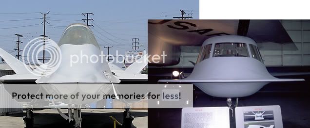
Yup,and take Tacit Blue, turn it upside down,shrink it a bit, and you have the TSSAM.
Originally posted by Aim64C
Interestingly enough - the more powerful YF-120 engines designed by General Electric were never tested in the YF-23.
Not true at all..The official supercruise speed for the YF-23/F-120 combo was "Very Fast at 41,000ft"
The F-120 powered PAV-2 also exhibited a lower fuel burn as well as greater acceleration throughout the test envelope. It had a MUCH greater percentage of it's total thrust in non-afterburner (dry) than the F-119.
Originally posted by FredT
Originally posted by Aim64C
Just stealth alon would not have made the decison. According to ben Rich and other sources the Skunk Works version of the stealth bomber was far stealthier than the B-2 but they still lost.
Have you seen pics of Lockheed's Senior Peg? That boom sticking out the back like that made the thing stand out like a sore thumb RCS-wise in comparison with the B-2.
Sometimes I see people on here attempting to make a cognizant point,but when you demonstrate that you can't spell (loose is the opposite of tight,people,just as there,they're and their are 3 entirely different words) then your credibility is shot. Just remember,you can't use spell check on a job application,and it DOES matter.
Originally posted by kilcoo316
Originally posted by Aim64C
Did it never occur to you that the nacelle protrusions above the wing will be producing downforce, and will remove alot (if not all plus some more) of the lift generated by the intakes and any lift generated by the forward fuselage (if it makes any at all).
Oh, and if you would, could you point out the lift generating mechanism for a intake that curves upward.
Actually,the production nacelles would have been far smaller and not as squared off as the prototypes,due to the elimination of the requirement for thrust reversers.Curvature in this intstance,on the TOP of the aircraft would actually increase lift,and decrease wing loading.
And as far as the upward curving intakes go,can you tell me how they are inferior to intakes that curve laterally? (ala F-22)
Originally posted by kilcoo316
So the YF-22 could deal with engine improvements allowing faster top speeds without a problem [above the 1.8 specified in the ATF requirements], but the YF-23 could not..
And you came to this conclusion how? That's a pretty substantial leap from your "calculations" to the real world you're taking to make that a factual statement. I'd like a cite on that please.
Originally posted by Canada_EH
what is the reason "exactly" for that shape? because the SR-71 has it 2.
Simply put, the chines are where the upper and lower curves meet. Those curves, carefully calculated, are major components of non-faceted VLO shaping. With optimization, the chine location contributes to aero as well.
reply to post by Wraith Wryder
lol that post was quite some time ago but yeah the chines are for LO tech reasons. The chines generate lift-bearing vortices at high angles of attack and reduce the aircraft's lateral radar signature.
[edit on 22/08/06 by Canada_EH]
lol that post was quite some time ago but yeah the chines are for LO tech reasons. The chines generate lift-bearing vortices at high angles of attack and reduce the aircraft's lateral radar signature.
[edit on 22/08/06 by Canada_EH]
Originally posted by EBJet
Originally posted by kilcoo316
Originally posted by Aim64C
Did it never occur to you that the nacelle protrusions above the wing will be producing downforce, and will remove alot (if not all plus some more) of the lift generated by the intakes and any lift generated by the forward fuselage (if it makes any at all).
Oh, and if you would, could you point out the lift generating mechanism for a intake that curves upward.
Actually,the production nacelles would have been far smaller and not as squared off as the prototypes,due to the elimination of the requirement for thrust reversers.Curvature in this intstance,on the TOP of the aircraft would actually increase lift,and decrease wing loading.
And as far as the upward curving intakes go,can you tell me how they are inferior to intakes that curve laterally? (ala F-22)
The intake shape actually was a point of concern in the F-23 proposal. It wasn't a fully "hiding" duct. Part of the engine front frame was visible from outside necessitating that frame to be treated for rf. This forced a departure from the engine design, Govenment Furnished Equipment, or mandated an additional front frame to hide the stock motor inlet - with additional maintenance and performance considerations - I don't remember how that finally shook out before Source Selection.
As far as humps, bumps and intake turns, the Aero groups for both teams were nothing less than incredible. Be confident that the aerodynamics were both balanced and as good as could be done with the requirements set. F-23 guys did get a bit stuck with the boat tail and rear deck with heat tiles, tho. BIG effort to change. The amazing thing to a lot of us was that they could confidently turn AND diffuse the intake flow at the same time, a former no-no, which shortened the intake ducts over prior design methods.
On some previous comments about F-23s on big Navy boats, that wasn't going to happen. The F-23 shape couldn't do it - would bump its butt, be mostly landing gear struts or land way too fast. Actually, the major, radical change in the Northrop/MacAir NATF proposal at the 11th hour to a double delta canard didn't help them a bit. Without some significant engineering to support the new config, it just wasn't viable.
The L/B/GD team proposal for basically a swing wing F-22, tho a little shorter and fatter, was much more mature and closer to the Air Force airplane's aero baseline. I "flew" Air Force F-22 handling characteristics in a carrier sim and it wasn't all that bad as it was. With no AOA indicator in the F-22 "tub," I just flew 130 KIAS and found glidepath correction to be a dead ringer for the F-4S - slower, of course. Pitch and roll were very crisp, as you'd expect of computerized "flippers," obvious even tho you just massage the stick on a stabilized approach - or should anyway. Learned later the approach could have been at 120 which would have given better power/glide path coupling and less of that hint of "float" before decel on power reduction. Still, it was pretty sweet as it was, not at all unacceptable.
Further - and sorry if this tinkles in anyone's Wheaties - both YF-23 and 22 size performance were close enuff to not be significant. The demonstrated PAV speed were just that, all they did in the test program, not what they'd do with the heaters on. The Ps (P sub s, specific excess power) curves were enormous compared to anything else you can name. They both had the power to melt themselves arodynamically long before running out of gas. Needless to say, that wasn't in the Test Plan.
Hope this adds some clarity. There's more if you like, UNCLAS to boot.
Originally posted by EBJetActually,the production nacelles would have been far smaller and not as squared off as the prototypes,due to the elimination of the requirement for thrust reversers.Curvature in this intstance,on the TOP of the aircraft would actually increase lift,and decrease wing loading.
And?
Unless your changing the placement of the nozzles they will still protrude that much above the wing.
Thus, they will still produce a significant downforce.
Originally posted by EBJet
And as far as the upward curving intakes go,can you tell me how they are inferior to intakes that curve laterally? (ala F-22)
Because laterally curving intakes only generate drag, not downforce and drag.
Originally posted by EBJet
And you came to this conclusion how? That's a pretty substantial leap from your "calculations" to the real world you're taking to make that a factual statement. I'd like a cite on that please.
Go google Mach cone.
Those "calculations" as you term them, brutally simple they may be, but they are applied to aircraft design in the conceptual stage (and that shape is automatically carried forward from there for refinement in detail design).
Go grab a top down schematic of the YF-23 and work it out yourself. If you find your numbers different, post them up.
If the top-view-mach-cone calc comment was referring to earlier discussion of F23 max speed, two things are relevant:
1. That's mostly correct. You can take a planform, work the 2D mach angle equation backwards and get mighty close to Vmax. Works real well for A-11/YF-12A/SR-71
but...
2. The F23 wasn't really built that way. More things come to the design table than Vmax. The airplane was mach limited by material temp tolerances, not any concern for sticking the wing tips thru the leading shock. To allow it to go as fast as the motors and aero could push it would have run the cost even farther off the page than it is. Plus, radome performance, bandpass & distortion, would have become even more of an issue. And since there really isn't a real reason to go so fast, it was an early trade.
When you specify that a machine has to be able to fit in a TabV shelter, max dimensions are basically set. (Zoomies are real big on folding wings) From there, arranging various components and volumes becomes an iteration game within the aero allowables, RCS budget, et al. We used to marvel a little once in a while how different the F22 and F23 looked when the design teams were given so many requirements the same - same motors, weapons volume, fuel volume, driver and seat sizes, avionics architecture, performance numbers and signature thresholds. There were even some real notable differences in the areas of concern to the 2 teams. One would say they just couldn't do a particular thing, mostly RF signature items, and the other would consider that same thing a low- or no-risk item.
So, the plan view mach angle calc post is correct (if I understood the meaning correctly), it's just not as applicable to these as with some other airplanes.
W^2
Originally posted by kilcoo316
Originally posted by EBJet
And you came to this conclusion how? That's a pretty substantial leap from your "calculations" to the real world you're taking to make that a factual statement. I'd like a cite on that please.
Go google Mach cone.
Those "calculations" as you term them, brutally simple they may be, but they are applied to aircraft design in the conceptual stage (and that shape is automatically carried forward from there for refinement in detail design).
Go grab a top down schematic of the YF-23 and work it out yourself. If you find your numbers different, post them up.
What is Vmax?
You mean Vno/Vne?
I've never seen Vmax depicted as a V speed before, are you referring to V speeds?
Shattered OUT...
You mean Vno/Vne?
I've never seen Vmax depicted as a V speed before, are you referring to V speeds?
Shattered OUT...
No it's not... At least no from the flight lessons I learned, there are two kinds of max speeds, Vne and Vno.
Vne is the "Never Exceed" speed and Vno is the Maximum Structural Cruising speed. There are differences in both.
I actually went and checked, there is no such thing as a Vmax, there are V speeds with the word max in it, but those V speeds indicate something else.
V speeds are very confusing and difficult to learn.
Shattered OUT...
Originally posted by ShatteredSkies
No it's not... At least no from the flight lessons I learned, there are two kinds of max speeds, Vne and Vno.
Vmax is maximum design spd in SLF - its probably not referred to by pilots as much as engineers.
Even then, I'm not sure its a 'proper' technical term, its possibly a slang for another term.
new topics
-
Shocking Number of Voters are Open to Committing Election Fraud
US Political Madness: 23 minutes ago -
Gov Kristi Noem Shot and Killed "Less Than Worthless Dog" and a 'Smelly Goat
2024 Elections: 1 hours ago -
Falkville Robot-Man
Aliens and UFOs: 1 hours ago -
James O’Keefe: I have evidence that exposes the CIA, and it’s on camera.
Whistle Blowers and Leaked Documents: 2 hours ago -
Australian PM says the quiet part out loud - "free speech is a threat to democratic dicourse"...?!
New World Order: 2 hours ago -
Ireland VS Globalists
Social Issues and Civil Unrest: 3 hours ago -
Biden "Happy To Debate Trump"
Mainstream News: 3 hours ago -
RAAF airbase in Roswell, New Mexico is on fire
Aliens and UFOs: 4 hours ago -
What is the white pill?
Philosophy and Metaphysics: 5 hours ago -
Blast from the past: ATS Review Podcast, 2006: With All Three Amigos
Member PODcasts: 6 hours ago
top topics
-
A Warning to America: 25 Ways the US is Being Destroyed
New World Order: 13 hours ago, 21 flags -
Biden "Happy To Debate Trump"
Mainstream News: 3 hours ago, 7 flags -
Blast from the past: ATS Review Podcast, 2006: With All Three Amigos
Member PODcasts: 6 hours ago, 7 flags -
Mike Pinder The Moody Blues R.I.P.
Music: 6 hours ago, 7 flags -
James O’Keefe: I have evidence that exposes the CIA, and it’s on camera.
Whistle Blowers and Leaked Documents: 2 hours ago, 5 flags -
Australian PM says the quiet part out loud - "free speech is a threat to democratic dicourse"...?!
New World Order: 2 hours ago, 5 flags -
What is the white pill?
Philosophy and Metaphysics: 5 hours ago, 5 flags -
Ireland VS Globalists
Social Issues and Civil Unrest: 3 hours ago, 4 flags -
RAAF airbase in Roswell, New Mexico is on fire
Aliens and UFOs: 4 hours ago, 4 flags -
Putin, Russia and the Great Architects of the Universe
ATS Skunk Works: 9 hours ago, 3 flags
active topics
-
Gov Kristi Noem Shot and Killed "Less Than Worthless Dog" and a 'Smelly Goat
2024 Elections • 24 • : TimBurr -
Falkville Robot-Man
Aliens and UFOs • 4 • : Kurokage -
The functionality of boldening and italics is clunky and no post char limit warning?
ATS Freshman's Forum • 13 • : JonnyC555 -
Candidate TRUMP Now Has Crazy Judge JUAN MERCHAN After Him - The Stormy Daniels Hush-Money Case.
Political Conspiracies • 805 • : Vermilion -
Shocking Number of Voters are Open to Committing Election Fraud
US Political Madness • 1 • : YourFaceAgain -
-@TH3WH17ERABB17- -Q- ---TIME TO SHOW THE WORLD--- -Part- --44--
Dissecting Disinformation • 700 • : Thoughtful3 -
Putin, Russia and the Great Architects of the Universe
ATS Skunk Works • 26 • : RussianTroll -
Re-election Tactic - JOE BIDEN Hints He May Put Books in the Homes of Black People.
2024 Elections • 30 • : WeMustCare -
Australian PM says the quiet part out loud - "free speech is a threat to democratic dicourse"...?!
New World Order • 3 • : Athetos -
Biden "Happy To Debate Trump"
Mainstream News • 35 • : WeMustCare