It looks like you're using an Ad Blocker.
Please white-list or disable AboveTopSecret.com in your ad-blocking tool.
Thank you.
Some features of ATS will be disabled while you continue to use an ad-blocker.

A B757 hit the Pentagon, reported by GOFER06
page: 52share:
Originally posted in page 50 by: pale5218
Originally posted by: Zaphod58
A reply to: LaBTop
The hijackers knew about the FAA radar gaps through several ways. Every time the radars in those areas had problems the FAA put out a NOTAM. Those can be looked up online,even back then.
Even if they knew, I can't see how this even was an element of their plan.
1) they didn't use this tactic on the other flights, if they tried, it didn't work for those planes to go invisible.
2) the flight started the deviation from course before turning off transponder. It started a turn to the south off the filed airway.
3) how would they know they were in that area, distance from a fix? Time clocked from departure point?
I have a hard time buying this gap in radar as part of the plan. I could be wrong about this but I don't see this as a calculated effort by the hijackers, too many variables to rely on this.
I think it was just a beneficial coincidence. Other than the flight turning back through this area, is there any other indications that it wasn't a coincidence?
I'm not sure if I missed something?
I think you did,
www.abovetopsecret.com...
See my 9:20 and 9:24 remarks, and my radar specialist remarks, who do not believe for one moment that AAL77 and UAL93 were not found within a few minutes after transponder loss by their colleagues that day.
www.abovetopsecret.com...
See my radar holes remarks in there.
1. They did use that tactic, see this map :
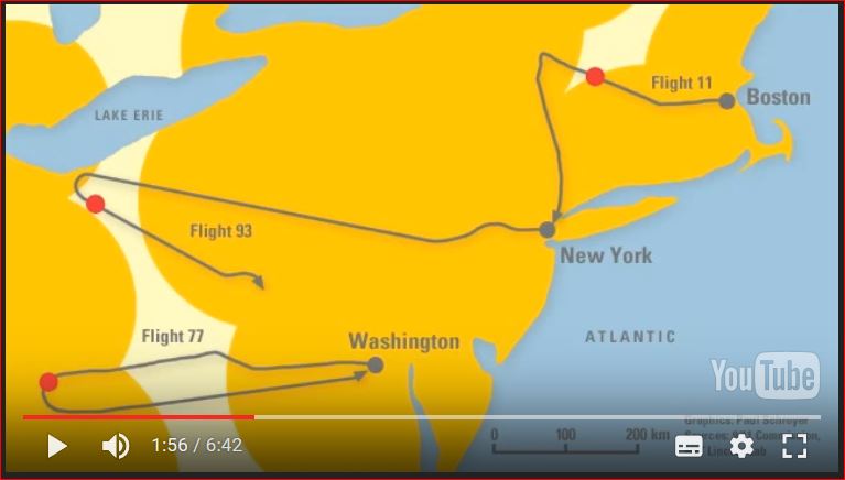
2. Flight 11, 175, 77 and 93 were all lost by FAA controllers in the crucial minutes, and quite some time thereafter, and these controllers were frantically searching in the wrong directions, on a guessed straight extension of their former flight paths.
Military and perhaps also FAA controllers had shortly after that however some primary targets on their scopes, but had no idea what planes from which airlines it were, after the initial target losses when the transponders were switched off.
Then some fake Flight 11 warning, as being still airborne, complicated things even more, and then another fake message that Flight 77 was flown in one of the Towers topped the whole chaotic situation for radar controllers off.
3. These "hijackers" didn't know, they were part of a "WWII-type England Spiel", probably played against them by the CIA, NSA, ONI, or whatever small but powerful faction of those agencies, secretly operating their 9/11 false flag operation, and were probably briefed before boarding, to just miss their targets as a warning to - who?
Fill in the gap as you wish.
F.ex. for the softies, by the hawks in Congress, or for the President by the Vice President, or whatever other logical sounding offered reason.
And then, in the last few seconds, all pilots understood that they could not interact with their planes' hardware anymore, and in these crucial 5 seconds or so, a totally panicking rooky pilot, realizing he's just a patsy and seeing his final place of burial come racing at him, would not know at all what to do in those last few seconds.
Even a seasoned airlines captain could only go for the breakers under the closed floor panel, in the electronics bay. And these 9/11 false flag planners would have made it completely impossible to find a solution for those hijacker pilots in these last few seconds, while seated in their hijacked pilot seats.
Show me if anybody thinks this overruling of some pre-installed remote-radio-controlled or distance-triggered or laser-triggered steering-hardware can be done in those last 5 seconds, when you see that target enlarging itself in your windscreen. They were simple patsies and sacrificed for the HUGE political and financial gains that resulted from their deaths and the deaths of all those innocent victims.
edit on 8/5/17 by LaBTop because:
Added another post link.
edit on 8/5/17 by LaBTop because: Forgot Flight UAL175 was gone off-radar too, see my post on page 48 :
www.abovetopsecret.com...
A reply to: pale5218
Again, I wholeheartedly agree with your reasoning, IF you believe in the OS.
If you do not, it's not such a farfetched idea that the same 9/11 planners could have influenced all your reasons, by having just one crucial person in the right place. Or perhaps two. Or three, or whatever how many.
If you realize that this was the biggest false flag operation after WWII, you also realize that all necessary complotting individuals were made instant multimillionaires, after they did their jobs. And probably got promoted too, to very high positions with the usual benefits.
Well, what a coincidence, ALL these crucial military brass got not sacked or imprisoned, no, they ALL got promoted.
a reply to: LaBTop
I watched an admiral back channel the purchase of a C-40, without going through the Pentagon, and not even get investigated. He retired with a full pension. And other flag officers that were investigated for sexual harassment and rape retire at one rank below where they were at the time, with honors and pension.
You've obviously never heard of the ring knocker societies. Short of murdering someone on camera, once you reach flag rank, you're golden. It doesn't matter what happens, even if you get fired from your position you'll end up with full honors at retirement, and firing someone from a command usually requires someone extremely high to be extremely upset with you. Otherwise you just get transferred early to a new position.
www.abovetopsecret.com...
It's even sillier when you take in account that that steep 330 degrees downward turn was flown without ANY auto pilot functions on.
By the way, the PfTruth notion that the plane flew near 500 MPH is not true, if you use the "recovered" DFDR data, you find around 280 to 320 MPH as speeds in that downward spiraling turn. Which is easily doable WHEN autopilot functions were on.
But that same DFDR says these were switched off 10 minutes before and never came on again. And we have several 10,000 flight hrs experienced 757 pilots at hand, that all said they could not copy that 330 degree turn at the first try, when seated in one of their companies professional flight simulators....
And then when it came out from that turn and accelerated to 500 MPH, it lined up perfectly for a straight line flight path hit at column 14 in the Pentagon west wall.
A lot of impossibilities and perfections we do not believe in, at all.
Salander : You may be willing to give Hanjour superhuman status, superpilot status and skills, but I am not. Numerous line pilots are on the record saying they could not fly that maneuver Hanjour did, and I'm very sympathetic to the statements of those airline pilots because I am a pilot myself, including flight instructor, and it is absurd to claim that somebody with Hanjour's reputation could do that. Downright silly.
It's even sillier when you take in account that that steep 330 degrees downward turn was flown without ANY auto pilot functions on.
By the way, the PfTruth notion that the plane flew near 500 MPH is not true, if you use the "recovered" DFDR data, you find around 280 to 320 MPH as speeds in that downward spiraling turn. Which is easily doable WHEN autopilot functions were on.
But that same DFDR says these were switched off 10 minutes before and never came on again. And we have several 10,000 flight hrs experienced 757 pilots at hand, that all said they could not copy that 330 degree turn at the first try, when seated in one of their companies professional flight simulators....
And then when it came out from that turn and accelerated to 500 MPH, it lined up perfectly for a straight line flight path hit at column 14 in the Pentagon west wall.
A lot of impossibilities and perfections we do not believe in, at all.
A reply to: Informer1958
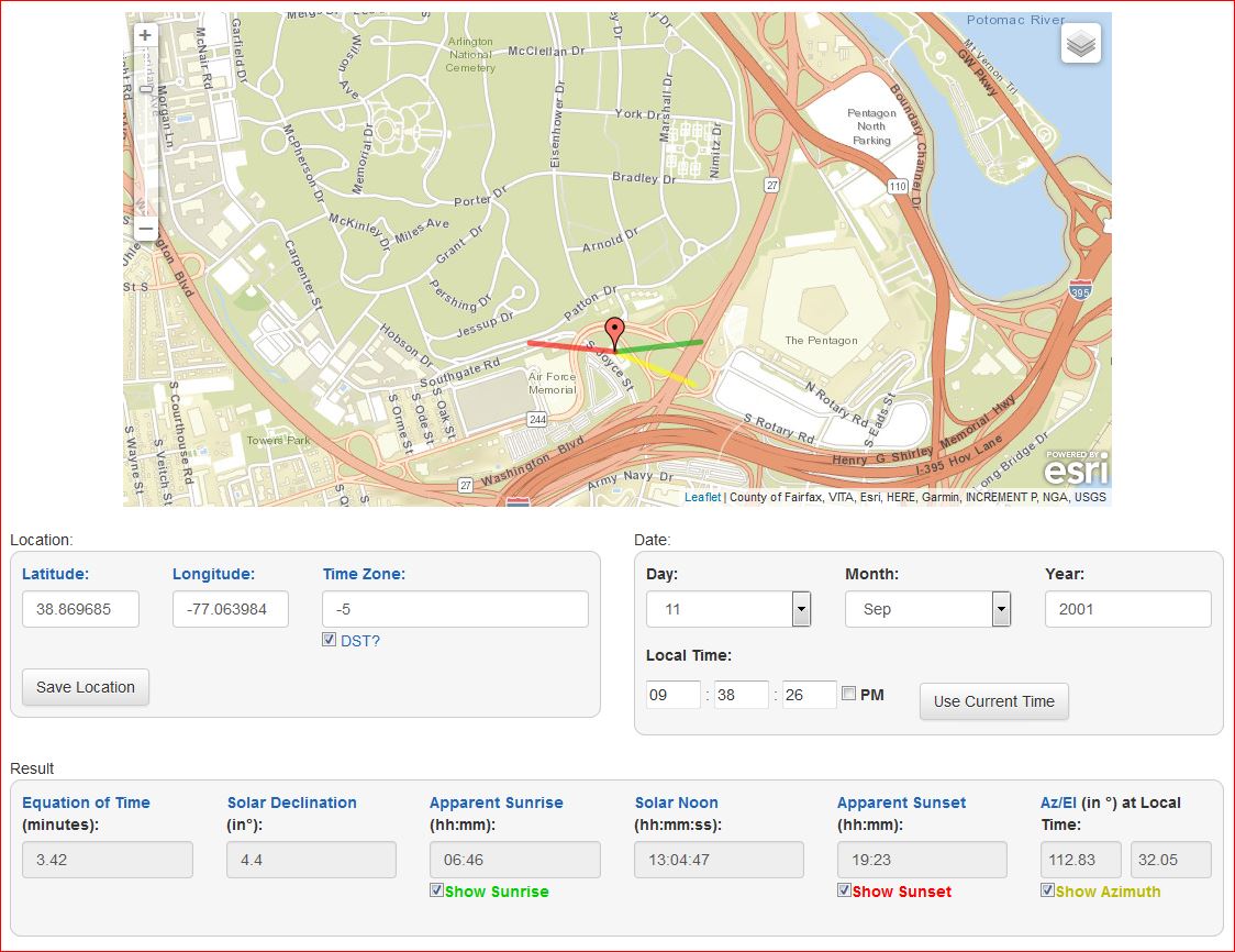
I find the deafening silence also impressive, after I asked for a sunlight reflection analysis on the glass sliding roof, side-windows or front screen of that just put in motion, police cruiser, that stood first parked and then slowly rode away from its position just NW of the left canopy pole in the CITGO video. Just as the intens sunlight reflection-flash on the northern canopy ceiling was registered, and 1 second later ALL the visitors and the counter personnel ran to that eastern door to look at the smoke column rising from the Pentagon's west wall.
Just take the suns azimuth position at 09:38, and see if a NoC or a SoC flying silvery, shiny AAL plane could reflect such a beam of sunlight down to that police cruiser its windows or roof surfaces, back up to that ceiling to cause that flash.?
The most amazing thing however, in that CITGO video, is the total absence of the view of that canopy camera, that hung under the NWestern corner of that northern canopy, with a full sight of the whole NoC flight path, up to impact.
The gas station manager later in 2006 told the CIT team, that that camera position was PLAYING onscreen on 9/11, but was absent from the FOIA freed CITGO surveillance cams video. She remembered that detail for 5 long years, so it must have upset her quite a bit.
AND, the FBI screwed exactly that camera off the ceiling, and it was never replaced again..... how about that for obstruction of justice.?
edit
on 8/5/17 by LaBTop because: inserted : the view of that canopy camera.
A reply to: LaBTop
Pilgrum, I'll help you out with some more detailed drawings, pictures and texts.
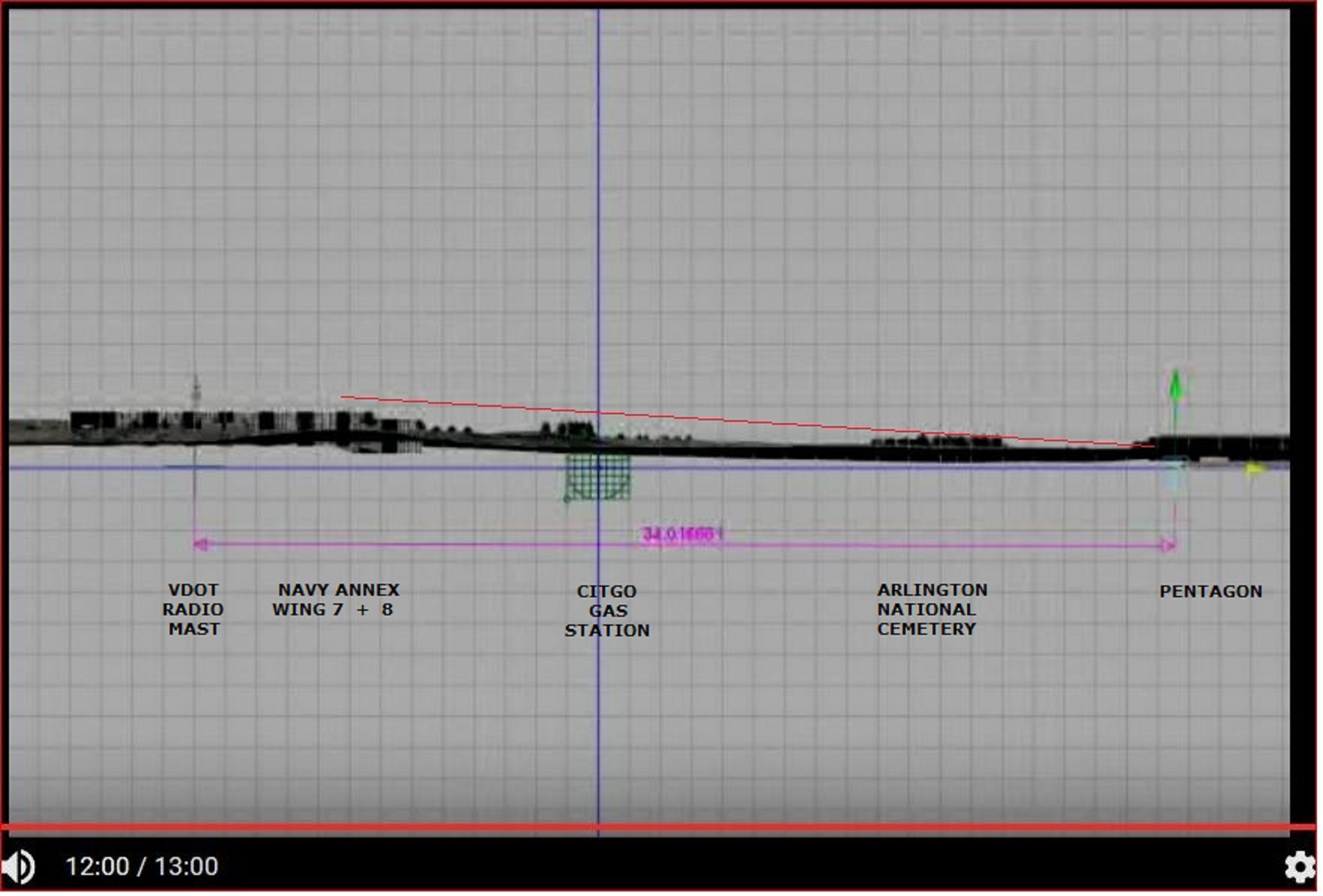
USGS terrain profile :
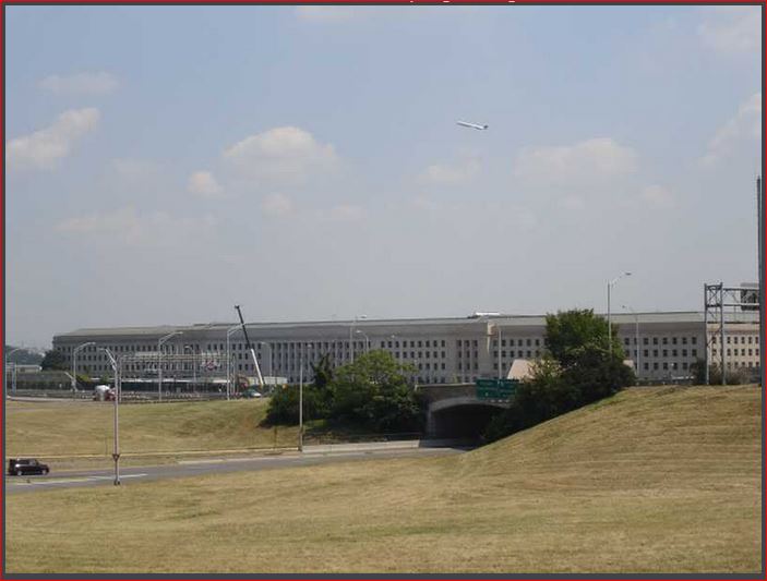
This is a helpful picture too, shot by the CIT team in 2006, all cut light poles are in it, and the impact was between the fourth and fifth window, visible just above the left part of that overpass bridge railing, those windows are to the right of that 3 stories high indent in the facade :
i14.photobucket.com...
Could anybody please explain to us, how that right wing or wing tip cut through that pole 1 between 17 and 23 ft high of its height of 40 ft, without cutting both tree tops at both sides of that overpass bridge railing.?
And without smashing its fuselage body through that railing, when its wing tips at 825 KMH were flexed up from its normal position on the tarmac (at 2/3 the height of the cabin's 4 m diameter = 2.67 m)? Do you think these wing tips weren't even flexed up a mere 0.50 m extra, when that pilot tried to level off to be able to fly straight over the lawn to leave that horizontal smoke turnings.?
That right wing's or right wing tip cut, is about half way up that pole 1, to make it easier to try to imagine it....
This is an interesting animated GIF by Craig Ranke from CIT; the parallel to the lawn moving smoke trail is best to see like it is done by him in this animation of several screenshots from the DoD its FOIA freed two security boots cams videos, and it then shows this result :
lytetrip's Animated GIF
Pilgrum, I'll help you out with some more detailed drawings, pictures and texts.
USGS terrain profile :
This is a helpful picture too, shot by the CIT team in 2006, all cut light poles are in it, and the impact was between the fourth and fifth window, visible just above the left part of that overpass bridge railing, those windows are to the right of that 3 stories high indent in the facade :
i14.photobucket.com...
Could anybody please explain to us, how that right wing or wing tip cut through that pole 1 between 17 and 23 ft high of its height of 40 ft, without cutting both tree tops at both sides of that overpass bridge railing.?
And without smashing its fuselage body through that railing, when its wing tips at 825 KMH were flexed up from its normal position on the tarmac (at 2/3 the height of the cabin's 4 m diameter = 2.67 m)? Do you think these wing tips weren't even flexed up a mere 0.50 m extra, when that pilot tried to level off to be able to fly straight over the lawn to leave that horizontal smoke turnings.?
That right wing's or right wing tip cut, is about half way up that pole 1, to make it easier to try to imagine it....
This is an interesting animated GIF by Craig Ranke from CIT; the parallel to the lawn moving smoke trail is best to see like it is done by him in this animation of several screenshots from the DoD its FOIA freed two security boots cams videos, and it then shows this result :
lytetrip's Animated GIF
I get a tad bit tired of all these OS defenders, who categorically deny to even think about doing some homework too, they are just bench sitters with
very little imaginary skills, so, let's dump it all into this thread, so pale5218 get some rewards for his gallant neutral stance answers :
This is a very helpful but complicated mathematical tool to predict wing flexes of metallic, composite and CNT-based composite wings :
mdolab.engin.umich.edu...
They use a lot of assumptions, to still arrive at a reasonable accurate calculation for critical loads.
Do view figures 2 to 9 and accompanying texts, to grasp the basics.
Metallic wings had smaller wingspans than composite ones. Our B757-200 had a 38 m wingspan. One wing, from center beam to wing tip was 19 meters wide.
This is a very helpful but complicated mathematical tool to predict wing flexes of metallic, composite and CNT-based composite wings :
mdolab.engin.umich.edu...
Page 1 of 24, Introduction :
Current and future composite material technologies have the potential to greatly improve the performance of large transport aircraft. However, the coupling between aerodynamics and structures makes it challenging to design optimal flexible wings, and the transonic flight regime requires high fidelity computational models. We address these challenges by solving a series of medium- and high-fidelity aerostructural optimization problems that explore the design space for the wing of a large transport aircraft. We consider three different materials: aluminum, carbon-fiber reinforced composites and an hypothetical composite based on carbon nanotubes. The design variables consist of both aerodynamic shape (including span), and structural sizing, as well as ply angle fractions in the case of composites. Pareto fronts with respect to takeoff weight and fuel burn are generated. The
wing performance in each case is optimized subject to stress and buckling constraints. We found that composite wings consistently resulted in lower fuel burn and lower structural weight, and that the carbon nanotube composite did not yield the increase in performance one would expect from a material with such outstanding properties. This was in part due to the minimum structural thickness constraint. For all materials, the minimum fuel burn wings were found to be longer, heavier, thinner, more flexible, and more lightly loaded than their minimum TOGW counterparts.
--snip--
In the structural parametrization for the metallic, composite and CNT-based composite wings, we split the wing structure into approximately flat panels that are analyzed and designed based on the stress state in the global finite-element model under a series of loading conditions. These panels consist of the structural components formed between the ribs and spars of the wing. In order to obtain an accurate estimate of the overall wing-box weight it is necessary to have a design tool that can correctly size panels over a wide range of loading conditions. The panels range from relatively lightly loaded at the tip to heavily loaded at the wing root. Over this range, it is most important to capture the behavior of the heavily loaded parts of the structure, since these structural components will have the greatest impact on the structural wing weight. --snip--
They use a lot of assumptions, to still arrive at a reasonable accurate calculation for critical loads.
Do view figures 2 to 9 and accompanying texts, to grasp the basics.
Page 17 etc. : B. --snip-- The objective is to identify differences in the resulting designs that are primarily caused by the higher fidelity aerodynamic analysis and the additional flexibility introduced through the airfoil shape variables.
Table 4 shows the data for the TOGW and fuel burn optimizations, and Figure 13 compares the pressure contours, airfoil shapes, structural thicknesses, spanwise lift distributions, twist distributions, and t/c distributions for these two optimizations.
--snip--
Page 22/24 : The optimal wing trends were consistent among the different materials: the minimum fuel burn wings were found to be longer, heavier, thinner, more flexible, and more lightly loaded than their minimum TOGW counterparts. The optimal composite wings exhibited larger spans than the metallic wings, and the CNT wings had even larger spans, reaching a maximum of almost 97 m for the minimum fuel burn case.
Metallic wings had smaller wingspans than composite ones. Our B757-200 had a 38 m wingspan. One wing, from center beam to wing tip was 19 meters wide.
By the way, Pilots for 9/11 Truth up to this date adhere themselves to their position (or, probably only Rob's) that you must take the top of the VDOT
mast as the starting height point in that dive path to the lawn.
I don't think that's true.
For several reasons, based on the Terry Morin, Sean Boger and Hemphill audios from the telephone interviews by their CIT team, and by Jeffrey from the PumpItOut forum, conducted with these three crucial eyewitnesses, who all three paint a flight path over the roof of the 8th Wing of the Annex.
Sean Boger additionally assured the interviewer, that he saw the plane coming to him in his Helipad control tower 35 m north of the impact point in column 14, from over a spot to the north of the CITGO gas station. Immediately nullifying the SoC official flight path through all those light poles. And then we have the rest of the 25 NoC witnesses.
And that's why I am, and always will be, a firm believer in my 230 MPH and 30 to 35 degrees banking flight path for AAL77, around the north side of the CITGO gas station, and then crossing Route 27 just south of those two low trees that were there on 9/11, passing with its left wing tip at about 2.5 to 3 m high over the rim of that concrete Helipad, and slashing with its right wing's wing tip aileron's outer sharp end through the roof of the generator trailer, just before its nose cone hit column 14 in the Pentagon's west wall, at the second floor slab's concrete floor rim.
a reply to: LaBTop
I know you attempted to explain this, but I didn't fully understand.
Why bother to fake light standard damage if a 757 actually hit the pentagon as you believe?
I mean, I can see the guys that somehow think a missile hit the pentagon have to account for the light poles, but as you believe a 757 did indeed hit the pentagon, there would be no reason to fake the light pole damage would there?
For the MS flight sim bashers, B757-200 flight-sims with realistic wing flex :
www.fspilotshop.com...
qualitywingssim.com...
Review of the Quality Wings Ultimate 757 Collection.
For the more math oriented readers :
Question how to calculate wing flex for use in a self developed Flight simulator program :
femci.gsfc.nasa.gov...
So, we carefully assume a +/- 1 G acceleration at the period of leveling off, in front of pole 1, or behind pole 1.
And then he shows 6 basic formulas to calculate a very precise G forces diagram over a known time period and known and measured inputs, which we don't have if you do not believe at all what the OS story tells us.
However, if you still believe it, you have all the G-forces data from the by Warren Strutt decoded last 6 seconds. Knock yourself out with those values.
By the way, in that "recovered" DFDR from AAL77, did you find increasing G-forces implicating a leveling-off near that famous light pole 1........?
Wait, I'll help you out, since self reflection is quite rare in this forum, for OS trusters :
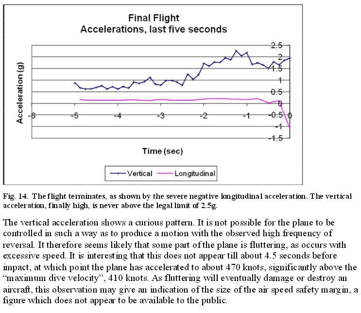
Damn, that's quite a vertical G-force increase at the 2.5 seconds to impact point, ain't it so...?
In fact, it starts already at the 3.5 seconds to impact point.
Its a whopping 0.5 to 2.25 G increase in G ...... in those last 3.5 seconds, he must have pulled with all his might at that steering column.
I repeat, I do believe Warren found these data points, he was set up to find them, since if the OS should have come up with those, nobody would have believed them, now, they have a patsy they can point at, if other proof nullifies Warren's findings. (The OS never admitted themselves to Warren's additional 5 seconds findings.... )
www.fspilotshop.com...
qualitywingssim.com...
* Realistic XML controlled Wingflex, reacting to turbulences.
Flight Dynamics:
* Realistic Flight Model.
* Developed based on real Level-D Simulators and tested by real life Pilots.
Review of the Quality Wings Ultimate 757 Collection.
For the more math oriented readers :
Question how to calculate wing flex for use in a self developed Flight simulator program :
femci.gsfc.nasa.gov...
Calculating Grms
(Root-Mean-Square Acceleration)
It is very easy to describe the Grms (root-mean-square acceleration, sometimes written as GRMS or Grms or grms or grms) value as just the square root of the area under the ASD vs. frequency curve, which it is. But to physically interpret this value we need to look at Grms a different way. The easiest way to think of the Grms is to first look at the mean square acceleration.
Mean-square acceleration is the average of the square of the acceleration over time. That is, if you were to look at a time history of an accelerometer trace and were to square this time history and then determine the average value for this squared acceleration over the length of the time history, that would be the mean square acceleration. Using the mean square value keeps everything positive.
The Grms is the root-mean-square acceleration (or rms acceleration), which is just the square root of the mean square acceleration determined above.
If the accelerometer time history is a pure sinusoid with zero mean value, e.g., a steady-state vibration, the rms acceleration would be .707 times the peak value of the sinusoidal acceleration (if just a plain average were used, then the average would be zero). If the accelerometer time history is a stationary Gaussian random time history, the rms acceleration (also called the 1 sigma acceleration) would be related to the statistical properties of the acceleration time history (you may have to refresh your probability and statistics knowledge for this):
68.3% of the time, the acceleration time history would have peaks that would not exceed the +/- 1 sigma accelerations.
95.4% of the time, the acceleration time history would have peaks that would not exceed the +/- 2 sigma accelerations.
99.7% of the time, the acceleration time history would have peaks that would not exceed the +/- 3 sigma accelerations.
There is no theoretical maximum value for the Gaussian random variable; however, we typically design to 3 sigma since it would only be theoretically exceeded 0.3% of the time. In addition, from a practical point of view, we know that it would be physically impossible to achieve unreasonably high sigma values.
So, we carefully assume a +/- 1 G acceleration at the period of leveling off, in front of pole 1, or behind pole 1.
And then he shows 6 basic formulas to calculate a very precise G forces diagram over a known time period and known and measured inputs, which we don't have if you do not believe at all what the OS story tells us.
However, if you still believe it, you have all the G-forces data from the by Warren Strutt decoded last 6 seconds. Knock yourself out with those values.
By the way, in that "recovered" DFDR from AAL77, did you find increasing G-forces implicating a leveling-off near that famous light pole 1........?
Wait, I'll help you out, since self reflection is quite rare in this forum, for OS trusters :
Damn, that's quite a vertical G-force increase at the 2.5 seconds to impact point, ain't it so...?
In fact, it starts already at the 3.5 seconds to impact point.
Its a whopping 0.5 to 2.25 G increase in G ...... in those last 3.5 seconds, he must have pulled with all his might at that steering column.
I repeat, I do believe Warren found these data points, he was set up to find them, since if the OS should have come up with those, nobody would have believed them, now, they have a patsy they can point at, if other proof nullifies Warren's findings. (The OS never admitted themselves to Warren's additional 5 seconds findings.... )
A reply to: D8Tee
Use LOGIC :
if one believes in 25 NoC eyewitnesses and heaps of other proven false official story details, then the official explanation for the Pentagon attack is also for most of its details false, and since we have all these NoC flight path witnesses, those light poles MUST have been staged in advance, since not one sane planner would try to cut and place cut light pole parts on the lawn in brought daylight.
Thus that faking of 5 cut poles must have been done as close to 9/11 as was reasonably safe, in the darkness of the morning hours. I posted three photos with those yellow painted VDOT (Virginia Department Of Transportation) flat bed trailers used to transport poles, parked on peculiar places very near to cut light poles, on the day of 9/11.
They probably opted for such an abundance of PHYSICAL but FAKE evidence, that they could easily smother any opposition after 9/11/2001.
That held for a few years, then the doubt grew exponentially, after 2005 into 2006.
You can use the next drawings, after you shrink or expand them to the right size and to the scale as used by me.
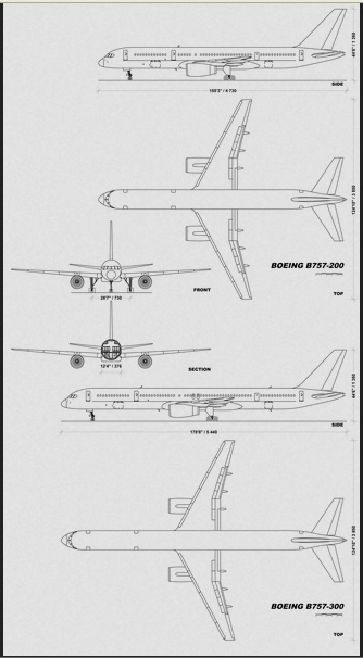
NOTE both wing tip positions in the lowest drawing, it's at 2/3 of the cabin height when parked on the runway :
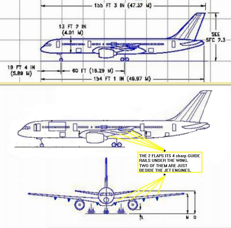
Wingspan B757-200 = 38.0 m (124 ft 10 inch), included the 4 m cabin diameter.
So half of the cabin diameter plus one wing length is :
38/2 = 19 m, or, 34/2 = 17 + 2 = 19 meter from the center of the fuselage to the wing tip, and the wing itself is 17 meter long/wide, aside a 4 meter wide hull.
NOTE both wing tip positions in the lowest drawing, it's at 2/3 of the cabin height when parked on the runway :
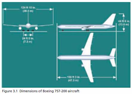
Wingspan B757-200 = 38.0 m (124 ft 10 inch), included the 4 m cabin diameter.
So half of the cabin diameter plus one wing length is :
38/2 = 19 m, or, 34/2 = 17 + 2 = 19 meter from the center of the fuselage to the wing tip, and the wing itself is 17 meter long/wide, aside a 4 meter wide hull.
The plane's attack angle of 60.25 ° true North, as proposed by the OS, cutting pole 1 and 2, and the other 3 poles, without the plane's right wing
tip also touching/cutting the VDOT camera mast and the 2 western corner their vertical poles, holding up that huge overhead traffic sign just beside
the VDOT (Virginia Department Of Transport) camera pole and pole 1, could result in the plane's right wing tip aileron making that gouge in the
generator trailer its roof, and its right jet engine cutting through the northwestern corner of the fence around the construction trailers area.
Here are some pointer pictures :
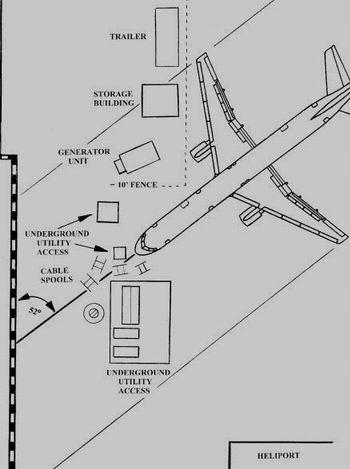
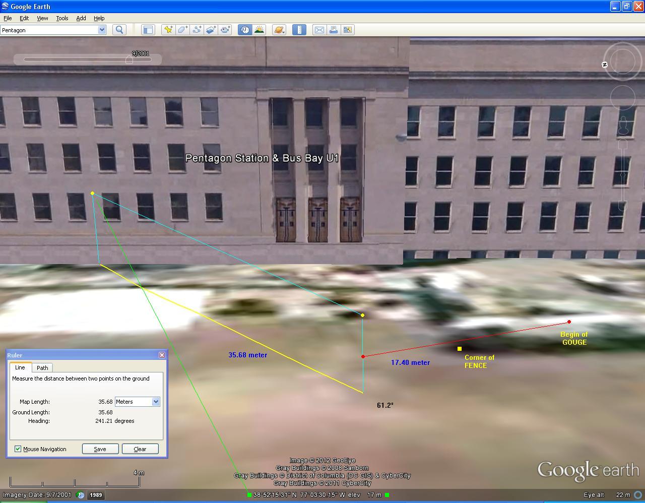
Note below, in the first drawing, that the distance from a B757-200 its center beam to its wing tip is 19 meters, and I measured the 17.40 meter distance from its center beam to that gouge in the generator trailer its roof. All in case the SoC flight path was right, and the NoC witnesses are all confused, mislead or they just simply lie. Which I do not believe in.
Note also, that this yellow dot on that western wall is the impact point, between those windows 4 and 5 and to the left of those three, 3 floor high recesses.
Right into column 14 and into the second floor slab, since we have a photo with fires in the wide impact hole, where you clearly see a chunk of floor slab taken out, about 2 to 3 meter deep and 3 to 4 meter wide, at the former column 14 position.
Note especially, that this is not a OS flight path of 60.25 degree true North, but a 61.2 degree true North line of attack, that follows from the second drawing and is calculated as the most viable flight path of a wingspan of 38 meters wide, and a single right wing span, from the center beam to the wing tip, of 19 meters.
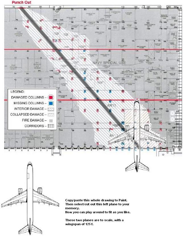
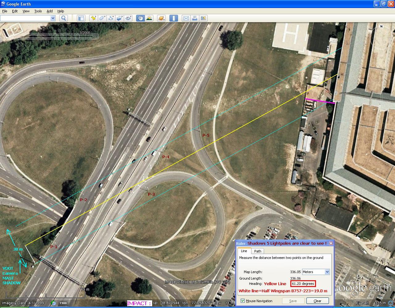
Which is the conclusion of the second drawing :
This is the most viable flight path drawing, with wings drawn in that are 19 meter wide, from center beam to wing tip.
WHILE missing at a few centimeters, with its right wing tip, that VDOT camera mast and the northwestern vertical pole upholding that huge overhead traffic signs board, spanning all of the width of Route 27.
A B757-200 its wing span is 125 ft 12 inch / 38 meter wide.
There is a meter-scale of 73 meters shown in the bottom-left corner of this Google Earth map, so you can compare its 38 m to my drawn in, 38 m wingspan on this map.
Note especially, that you can clearly see the REAL positions of all the light poles, since you see all their shadows on the ground.
And note also, that the purple line I drew perpendicular on the west wall is the real fence position of 9/11/2001, and not that black line adjacent to that white vent area.
Note also, that the point on that west wall where my yellow center beam line ends, is the exact nose cone impact point on column 14 :
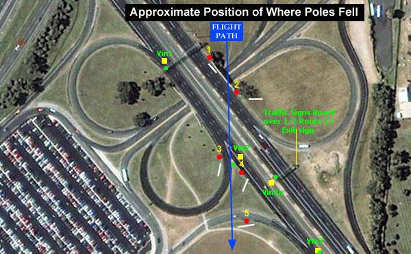
The below picture of fallen light poles positions found at lytetrip (Craig Ranke, CIT) his photobucket account :
Where light poles fell JPG, by lytetrip (Craig Ranke, CIT).
VDOT camera mast graphic JPG.
Here are some pointer pictures :
Note below, in the first drawing, that the distance from a B757-200 its center beam to its wing tip is 19 meters, and I measured the 17.40 meter distance from its center beam to that gouge in the generator trailer its roof. All in case the SoC flight path was right, and the NoC witnesses are all confused, mislead or they just simply lie. Which I do not believe in.
Note also, that this yellow dot on that western wall is the impact point, between those windows 4 and 5 and to the left of those three, 3 floor high recesses.
Right into column 14 and into the second floor slab, since we have a photo with fires in the wide impact hole, where you clearly see a chunk of floor slab taken out, about 2 to 3 meter deep and 3 to 4 meter wide, at the former column 14 position.
Note especially, that this is not a OS flight path of 60.25 degree true North, but a 61.2 degree true North line of attack, that follows from the second drawing and is calculated as the most viable flight path of a wingspan of 38 meters wide, and a single right wing span, from the center beam to the wing tip, of 19 meters.
Which is the conclusion of the second drawing :
This is the most viable flight path drawing, with wings drawn in that are 19 meter wide, from center beam to wing tip.
WHILE missing at a few centimeters, with its right wing tip, that VDOT camera mast and the northwestern vertical pole upholding that huge overhead traffic signs board, spanning all of the width of Route 27.
A B757-200 its wing span is 125 ft 12 inch / 38 meter wide.
There is a meter-scale of 73 meters shown in the bottom-left corner of this Google Earth map, so you can compare its 38 m to my drawn in, 38 m wingspan on this map.
Note especially, that you can clearly see the REAL positions of all the light poles, since you see all their shadows on the ground.
And note also, that the purple line I drew perpendicular on the west wall is the real fence position of 9/11/2001, and not that black line adjacent to that white vent area.
Note also, that the point on that west wall where my yellow center beam line ends, is the exact nose cone impact point on column 14 :
The below picture of fallen light poles positions found at lytetrip (Craig Ranke, CIT) his photobucket account :
Where light poles fell JPG, by lytetrip (Craig Ranke, CIT).
VDOT camera mast graphic JPG.
Got most of the pictures from this ATS thread, and its links to CIT :
Title : The downed light poles at the Pentagon were staged in advance.
www.abovetopsecret.com...
Interesting animated GIF by Craig Ranke from CIT, the smoke trail is best to see like this :
i14.photobucket.com...
Ingersoll Images Reveal Staged Light Pole & Cab Scene Minutes After Attack :
www.thepentacon.com...
It includes all hi-res Ingersoll pictures. Note the dome camera in this CIT video, on top of Navy Annex its Wing 8 corner.
See photo DSC_0408, time taken: 9:47.
See the same dome camera type on the roof rim, just above the impact point.? Still thinking the military has no additional video of the attacking plane.?
And read this :
He was in 2006 the VDOT's Operations Manager for Safety Service Patrol. He was in charge of road closures for road safety issues and potentially maintenance most notably of the light poles. He gave CIT all the Ingersoll hi-res pictures.
He left two little children and his young wife. Not really much reasons to end his life.
His colleague Ryan led CIT a few months later around on the VDOT its light pole depository yard :
VDOT tour of light poles :
www.youtube.com...
Tour of the Virginia Department of Transportation(VDOT) :
www.thepentacon.com...
Title : The downed light poles at the Pentagon were staged in advance.
www.abovetopsecret.com...
Interesting animated GIF by Craig Ranke from CIT, the smoke trail is best to see like this :
i14.photobucket.com...
Ingersoll Images Reveal Staged Light Pole & Cab Scene Minutes After Attack :
www.thepentacon.com...
It includes all hi-res Ingersoll pictures. Note the dome camera in this CIT video, on top of Navy Annex its Wing 8 corner.
See photo DSC_0408, time taken: 9:47.
See the same dome camera type on the roof rim, just above the impact point.? Still thinking the military has no additional video of the attacking plane.?
And read this :
In an extremely strange and suspicious twist that we can only pray is a coincidence, about a week after we had obtained the CITGO witnesses testimony on film, Christopher Landis committed suicide.
He was in 2006 the VDOT's Operations Manager for Safety Service Patrol. He was in charge of road closures for road safety issues and potentially maintenance most notably of the light poles. He gave CIT all the Ingersoll hi-res pictures.
He left two little children and his young wife. Not really much reasons to end his life.
His colleague Ryan led CIT a few months later around on the VDOT its light pole depository yard :
VDOT tour of light poles :
www.youtube.com...
Tour of the Virginia Department of Transportation(VDOT) :
www.thepentacon.com...
First, let's show you my 61.2 ° true North latest SoC official flight path calculation, the one that should have an attack angle of 60.25 ° true
North, like the ASCE Pentagon Damage Report mentioned.
It's a 1280 x 898 pixels one, so zoom in and out, as you like : (press 7x the Ctrl and + keys ).
And you will see that its right wing tip just misses that northern corner pole from the huge overhead traffic signs board. And then JUST cuts through pole 1.
Precisely what I said in my first posts about my subject, the cuts in pole 1 and 2.
My subject is not about the next cut poles, they are not really interesting for my explanation.
I did not specifically address the further cuts in the other 3 poles, since we do not have really conclusive photos of those 3. I guessed them to be at about 20 feet high.
The most important cut-height evidence is at pole 1, combined with the resulting fuselage belly bottom height above soil, of that B757-200, hanging between its two nearly maximum flexed up wing tips.
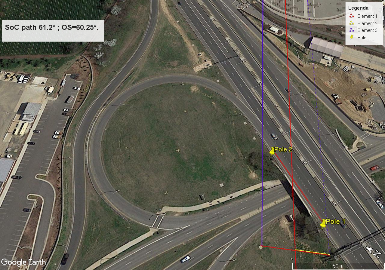
I will show you in my next aerial pictures the exact positions of all 5 light poles, and the plane's fuselage position and angle, and its right wing-tip while it cut through pole 1, while flying the by the OS story proposed 825 KMH towards the impact point on the west wall at column 14.
To let it fit these exact positions you need to honestly fit the NoC flight path to pole 1 and 2.
I measured them two, by pinpointing the pole 1 and 2 shadow bottoms, and thus found their real pole-bases besides both ends of the overpass its sand-stones railing.
I measured in Google Earth Pro the distance between both pole bases, its 52 meters.
I also drew the yellow 19 meter width of one wing which includes the 2 meters of half the fuselage width of 4 meters. And drew my 2 blue parallel lines that indicate the wing tip ends. And that shows the 38 meters wingspan.
The red center line is the center beam of the fuselage of a B757-200, that ends at column 14 at the second floor slab :
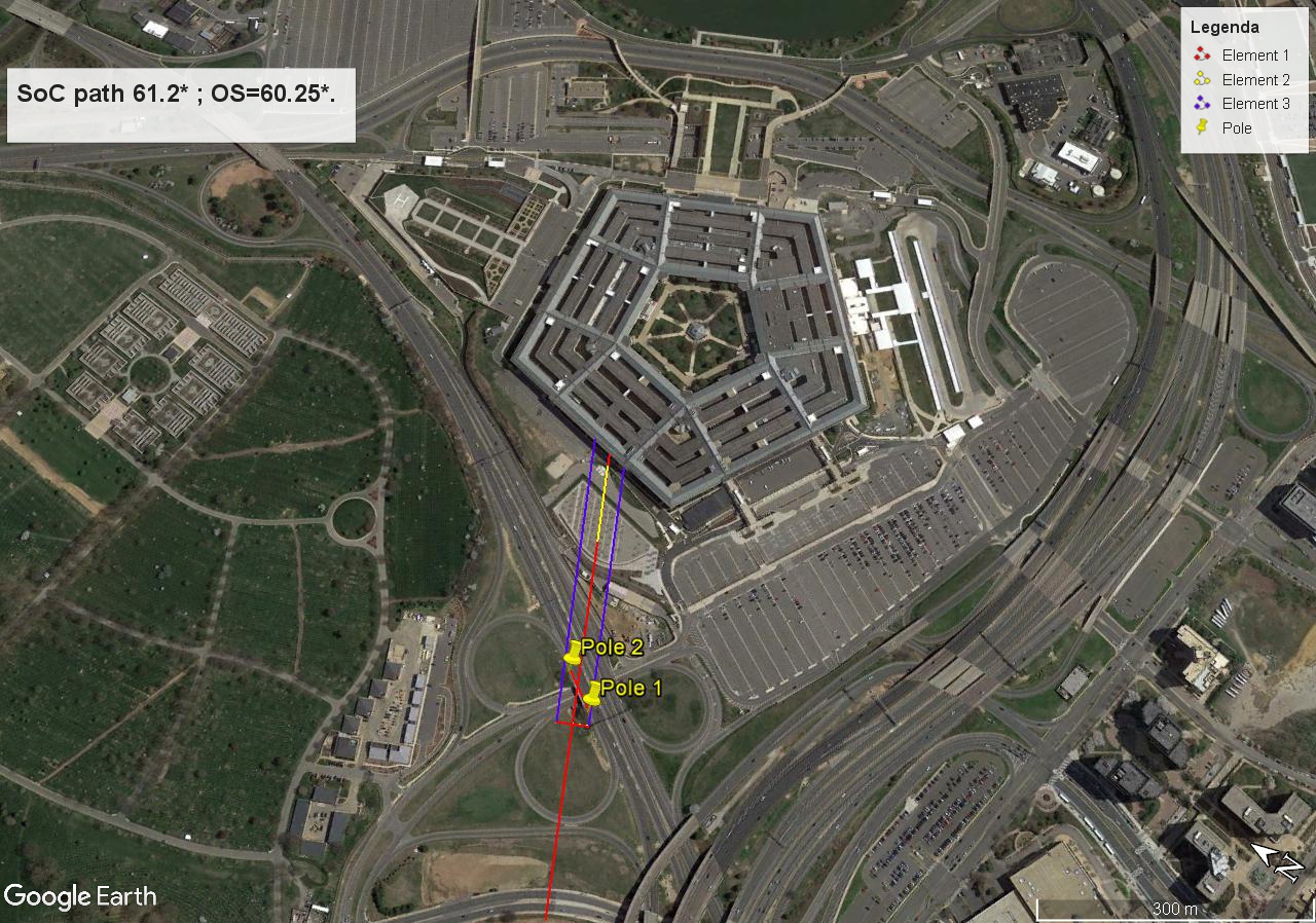
It were not the flexed up wing tips that cut through pole 2 and poles 3, 4 and 5.
Only through pole 1 where we have photos from, but sadly enough, I don't have photos of that pole 2 its cut parts. Anyone has them?
But as Adam Larson already hinted at, the imprint of both wings on the west wall indicated a 3 to 5 degrees uplifted right wing, so, it's not far fetched to assume that the plane was already in such a right wing up position, when it cut through pole 1.
It's a 1280 x 898 pixels one, so zoom in and out, as you like : (press 7x the Ctrl and + keys ).
And you will see that its right wing tip just misses that northern corner pole from the huge overhead traffic signs board. And then JUST cuts through pole 1.
Precisely what I said in my first posts about my subject, the cuts in pole 1 and 2.
My subject is not about the next cut poles, they are not really interesting for my explanation.
I did not specifically address the further cuts in the other 3 poles, since we do not have really conclusive photos of those 3. I guessed them to be at about 20 feet high.
The most important cut-height evidence is at pole 1, combined with the resulting fuselage belly bottom height above soil, of that B757-200, hanging between its two nearly maximum flexed up wing tips.
I will show you in my next aerial pictures the exact positions of all 5 light poles, and the plane's fuselage position and angle, and its right wing-tip while it cut through pole 1, while flying the by the OS story proposed 825 KMH towards the impact point on the west wall at column 14.
To let it fit these exact positions you need to honestly fit the NoC flight path to pole 1 and 2.
I measured them two, by pinpointing the pole 1 and 2 shadow bottoms, and thus found their real pole-bases besides both ends of the overpass its sand-stones railing.
I measured in Google Earth Pro the distance between both pole bases, its 52 meters.
I also drew the yellow 19 meter width of one wing which includes the 2 meters of half the fuselage width of 4 meters. And drew my 2 blue parallel lines that indicate the wing tip ends. And that shows the 38 meters wingspan.
The red center line is the center beam of the fuselage of a B757-200, that ends at column 14 at the second floor slab :
It were not the flexed up wing tips that cut through pole 2 and poles 3, 4 and 5.
Only through pole 1 where we have photos from, but sadly enough, I don't have photos of that pole 2 its cut parts. Anyone has them?
But as Adam Larson already hinted at, the imprint of both wings on the west wall indicated a 3 to 5 degrees uplifted right wing, so, it's not far fetched to assume that the plane was already in such a right wing up position, when it cut through pole 1.
a reply to: LaBTop
After researching the events into 911, It occur to me that the FBI had their hands in everything and many times after the FBI had access to something it was never seen again. This alone proves a cover up. If the OS was so true, then why would the FBI go to this length of hiding, and destroying critical evidence?
Just as you demonstrated about the NW western corner of the northern canopy video that was missing from the FOIA, to never be seen again.
BTW, thank you for sharing that information, every little bit helps in piecing this extraordinary puzzle together.
The most amazing thing however, in that CITGO video, is the total absence of the view of that canopy camera, that hung under the NWestern corner of that northern canopy, with a full sight of the whole NoC flight path, up to impact.
The gas station manager later in 2006 told the CIT team, that that camera position was PLAYING onscreen on 9/11, but was absent from the FOIA freed CITGO surveillance cams video. She remembered that detail for 5 long years, so it must have upset her quite a bit.
AND, the FBI screwed exactly that camera off the ceiling, and it was never replaced again..... how about that for obstruction of justice.?
After researching the events into 911, It occur to me that the FBI had their hands in everything and many times after the FBI had access to something it was never seen again. This alone proves a cover up. If the OS was so true, then why would the FBI go to this length of hiding, and destroying critical evidence?
Just as you demonstrated about the NW western corner of the northern canopy video that was missing from the FOIA, to never be seen again.
BTW, thank you for sharing that information, every little bit helps in piecing this extraordinary puzzle together.
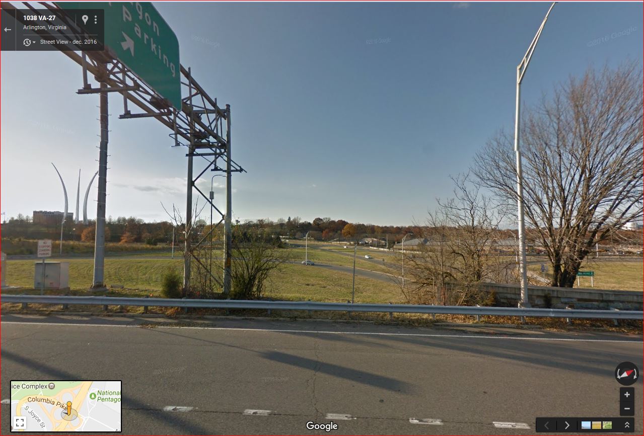
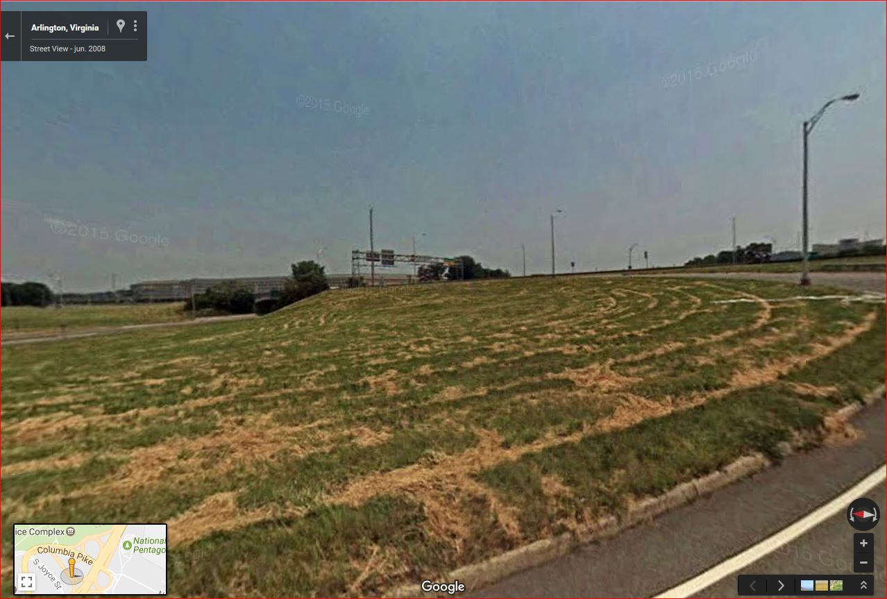
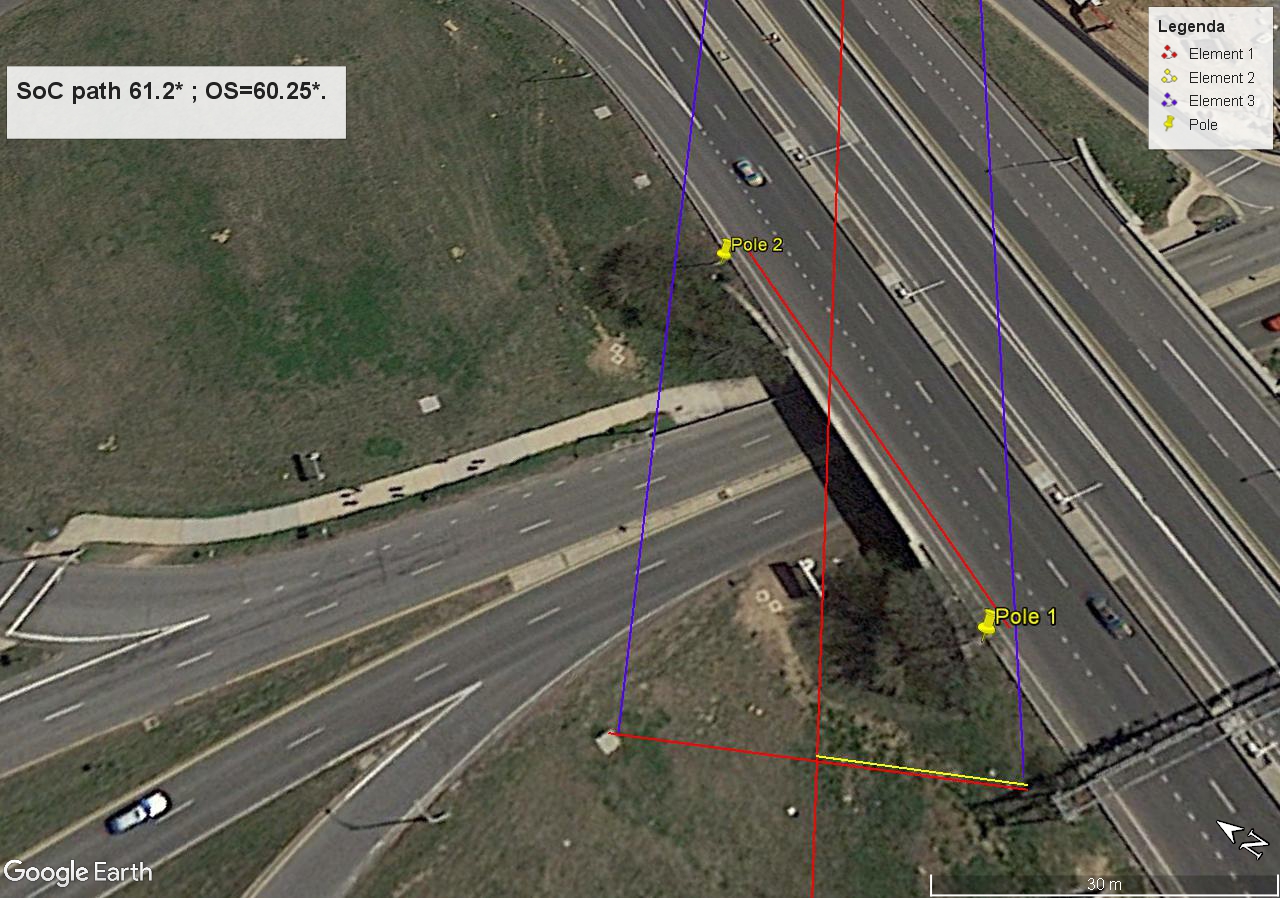
Pole 1 position beginning of overpass bridge wall.JPG :
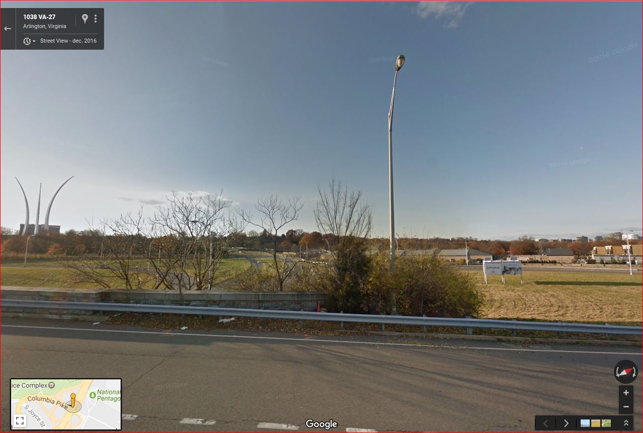
Pole 2 position-end of overpass wall.JPG :
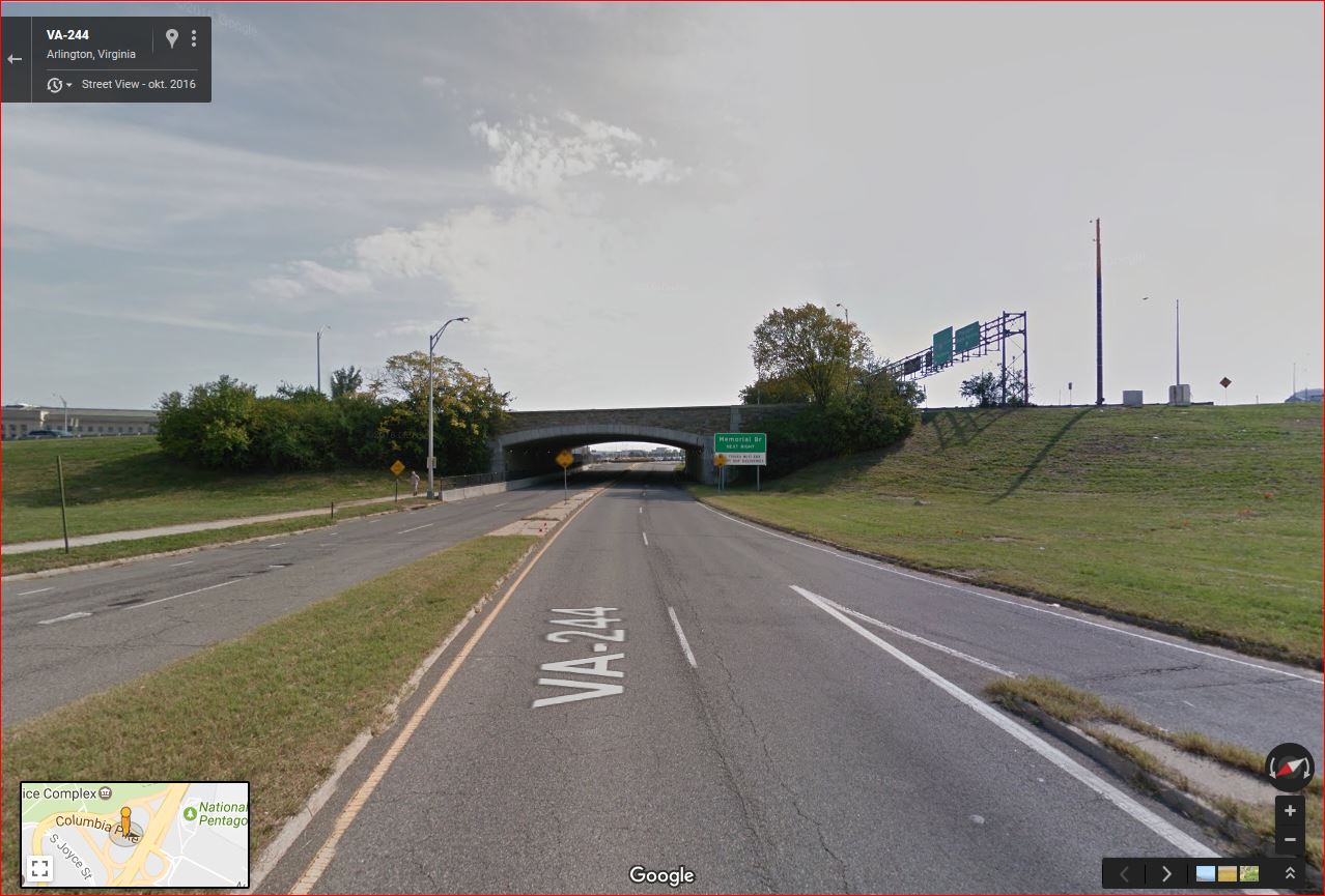
Overpass bridge Route 27 in 2016.JPG :
SoC flight path between pole 2 and 1 on overpass.JPG :
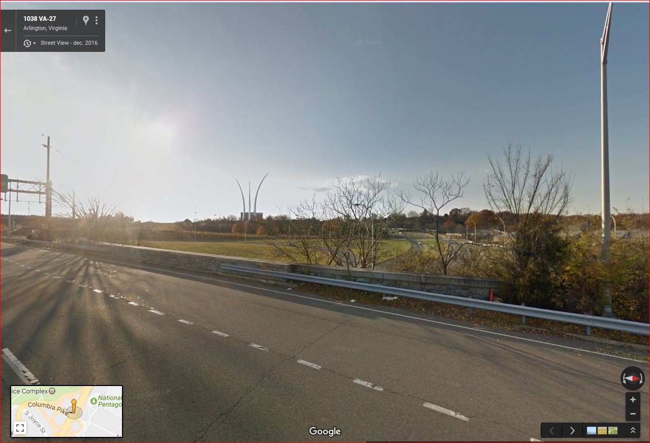
SoC flight path through pole 2 and 1 - 100 m S on exit ramp.JPG :
Sun azimuth 09112001 at CITGO gas station near Pentagon 09:38 :
CITGO canopy ceiling flash screen shot sucsession from Adam Larson blog.JPG :
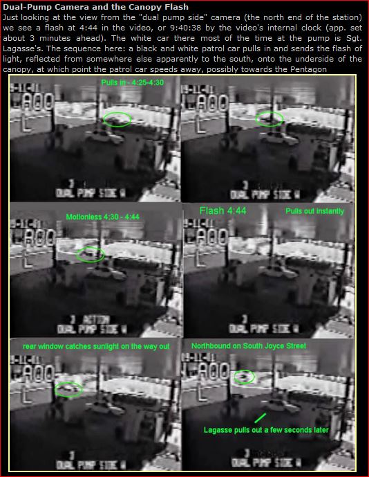
His fifth picture says it all, the rear window catches direct sunlight there from the still lowstanding southeastern sun, and does not reflect it to the ceiling at that spot. The 4:44 flash was thus reflected sunlight from AAL77 passing somewhere north at about 100 m up, as Sgt. Lagasse told us.
Pole-shadows- 1 and 2 cut by wing tips - zoomed to 50 m.jpg :
Pole-shadows- 1 and 2 cut by wing tips - zoomed to 30 m.jpg :
Pole-shadows- 1 and 2 cut by wing tips - zoomed to 30 m - Center pole.JPG :
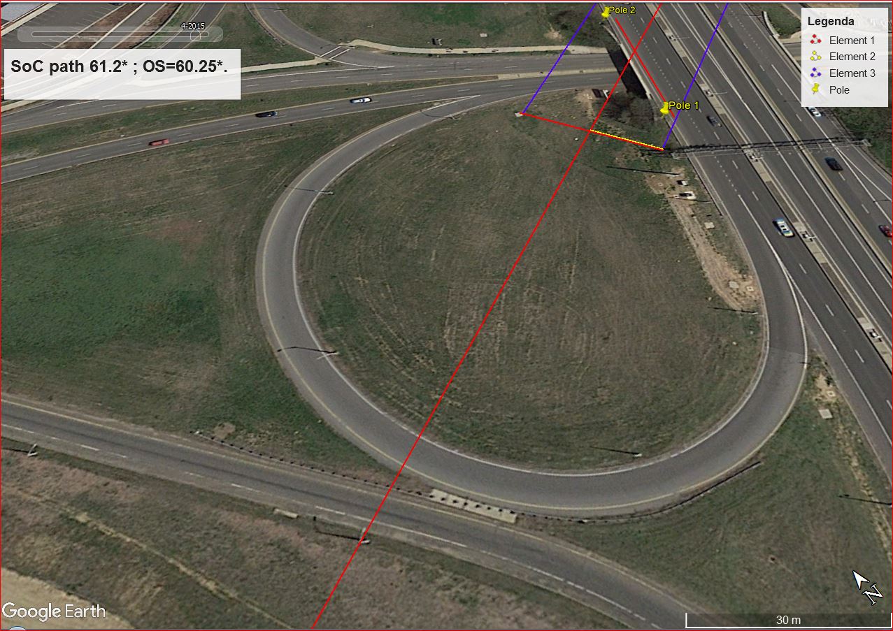
Note that above 40 ft / 12.2 m high light pole along that cloverleaf exit ramp.
The plane's fuselage bottom must have just missed it, to fit in the OS story.
Or NOT.?
Pole 2 position-end of overpass wall.JPG :
Overpass bridge Route 27 in 2016.JPG :
SoC flight path between pole 2 and 1 on overpass.JPG :
SoC flight path through pole 2 and 1 - 100 m S on exit ramp.JPG :
Sun azimuth 09112001 at CITGO gas station near Pentagon 09:38 :
CITGO canopy ceiling flash screen shot sucsession from Adam Larson blog.JPG :
His fifth picture says it all, the rear window catches direct sunlight there from the still lowstanding southeastern sun, and does not reflect it to the ceiling at that spot. The 4:44 flash was thus reflected sunlight from AAL77 passing somewhere north at about 100 m up, as Sgt. Lagasse told us.
Pole-shadows- 1 and 2 cut by wing tips - zoomed to 50 m.jpg :
Pole-shadows- 1 and 2 cut by wing tips - zoomed to 30 m.jpg :
Pole-shadows- 1 and 2 cut by wing tips - zoomed to 30 m - Center pole.JPG :
Note that above 40 ft / 12.2 m high light pole along that cloverleaf exit ramp.
The plane's fuselage bottom must have just missed it, to fit in the OS story.
Or NOT.?
Corrected text for earlier posts :
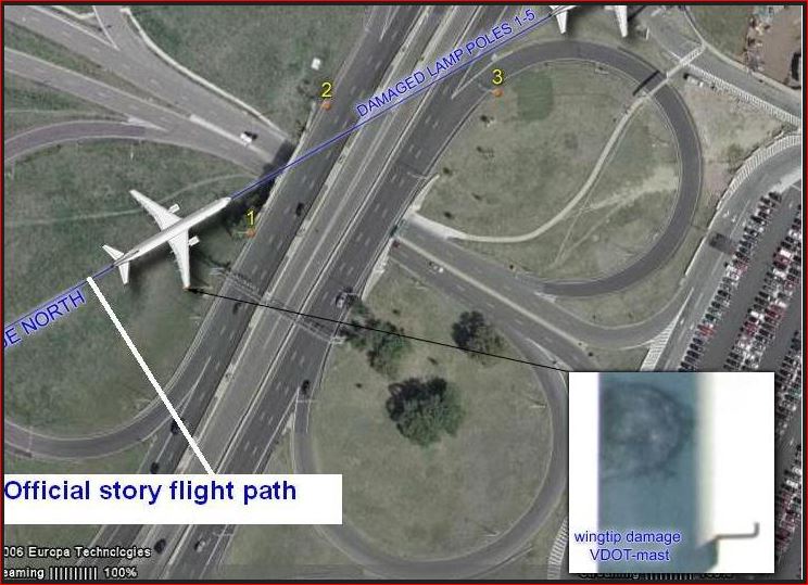
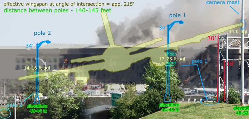
After re-viewing Adam Larson's confusing plane-drawing in his below picture, it's clear that he drew a far too-horizontal wing span position.
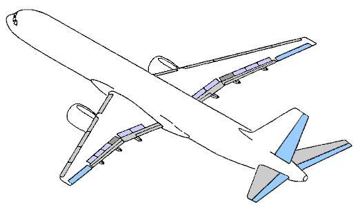
In rest, parked on the tarmac, the wing tips of a B757-200 are already at least 2.66 meters above its fuselage's belly bottom, see the bottom drawing, use a ruler to see that wing tips in rest, are at a 2/3rd height of the 4 meter diameter of the fuselage.
So, you still think that at that crazy proposed Official Story speed of 825 KMH in dense air, its wings half-way lengths and especially its wing tips, would not flex up an additional 0.34 meter / 1 feet .? :
Adam Larson's plane's right wing is far too far up, when it cut through his pole 1.
Which he placed far too far to the left btw, he indicated its right spot with his blue pole 1-line. He tried to get the cut in pole 1 as near to his "shaved" tree top as possible, to let his idea sink in, in the not so critical readers their minds.
He smuggled its right wing up an additional few feet to let its jet engine nacelle "cut-out" that tree top, which was not cut at all, but grew like that, or was trimmed like that by a maintenace worker long before it grew that high.
He also has the distance between pole 1 and 2 wrong, its 52 m, and not 42.67 m :
And then view this situation shot from 2006 by CIT :
i14.photobucket.com...
And then compare the above one with this below shown overhead situation picture that I took from lytetrip (Craig Ranke, CIT) his photobucket repository, titled "VDOT camera mast graphic JPG" :
And this below shown, much sharper Google Earth picture I took and filled in the correct 61.20 ° angle, indicated and set by Google Earth its yellow line, which is thus NOT the OS its ASCE Report's mentioned 60.25 ° flight path, which would however aim and be drawn-in, a bit lower, and would hit those just missed poles in my 61.20 ° angle (where the right wing tip is already very close to hitting those two other poles).
This sounds perhaps a bit arbitrary, since it seemed quite difficult to check if the impact point on column 14 is a correct assumption (it's where the chunk of concrete is missing in the second floor slab's front, as seen in an Ingersoll or someone's other picture), and one can doubt if it is utterly correct shown in Google Earth, but I took that impact point on column 14 from the below shown second picture, and I think its quite precise, I just extended the northern side of that rectangular shaped white venting area, you also see in this first below picture, to the Pentagon's west wall in there :
The impact position at column 14, seen from above the ground level in the above aerial picture (see its bottom line, its IMPACT : lat and lon values) was compared by me to the white square in front of it, which was the concrete venting area also visible in this below picture. Impact was at column 14 on the second floor slab, 4.26 meter above ground level there.
Note also my purple line, that's the real 9/11/2001 position of the northern fence line at that date, and not that black line adjacent to the white air-venting block.
After re-viewing Adam Larson's confusing plane-drawing in his below picture, it's clear that he drew a far too-horizontal wing span position.
In rest, parked on the tarmac, the wing tips of a B757-200 are already at least 2.66 meters above its fuselage's belly bottom, see the bottom drawing, use a ruler to see that wing tips in rest, are at a 2/3rd height of the 4 meter diameter of the fuselage.
So, you still think that at that crazy proposed Official Story speed of 825 KMH in dense air, its wings half-way lengths and especially its wing tips, would not flex up an additional 0.34 meter / 1 feet .? :
Adam Larson's plane's right wing is far too far up, when it cut through his pole 1.
Which he placed far too far to the left btw, he indicated its right spot with his blue pole 1-line. He tried to get the cut in pole 1 as near to his "shaved" tree top as possible, to let his idea sink in, in the not so critical readers their minds.
He smuggled its right wing up an additional few feet to let its jet engine nacelle "cut-out" that tree top, which was not cut at all, but grew like that, or was trimmed like that by a maintenace worker long before it grew that high.
He also has the distance between pole 1 and 2 wrong, its 52 m, and not 42.67 m :
And then view this situation shot from 2006 by CIT :
i14.photobucket.com...
And then compare the above one with this below shown overhead situation picture that I took from lytetrip (Craig Ranke, CIT) his photobucket repository, titled "VDOT camera mast graphic JPG" :
And this below shown, much sharper Google Earth picture I took and filled in the correct 61.20 ° angle, indicated and set by Google Earth its yellow line, which is thus NOT the OS its ASCE Report's mentioned 60.25 ° flight path, which would however aim and be drawn-in, a bit lower, and would hit those just missed poles in my 61.20 ° angle (where the right wing tip is already very close to hitting those two other poles).
This sounds perhaps a bit arbitrary, since it seemed quite difficult to check if the impact point on column 14 is a correct assumption (it's where the chunk of concrete is missing in the second floor slab's front, as seen in an Ingersoll or someone's other picture), and one can doubt if it is utterly correct shown in Google Earth, but I took that impact point on column 14 from the below shown second picture, and I think its quite precise, I just extended the northern side of that rectangular shaped white venting area, you also see in this first below picture, to the Pentagon's west wall in there :
The impact position at column 14, seen from above the ground level in the above aerial picture (see its bottom line, its IMPACT : lat and lon values) was compared by me to the white square in front of it, which was the concrete venting area also visible in this below picture. Impact was at column 14 on the second floor slab, 4.26 meter above ground level there.
Note also my purple line, that's the real 9/11/2001 position of the northern fence line at that date, and not that black line adjacent to the white air-venting block.
The last ones of the 5 cut-down lamp poles were cut by wings at a height of about 20 feet (6.10 meters), while the nose cone (6 ft/1.83m above the
wings, the fuselage is 4 m wide) impacted the second floor slab at about 14 feet high above ground level (4.26 meter), which is a 6 + 6 feet (2x1.83
meter) = 12 feet (3.66 meter) decrease in height over a circa 180 feet (54.8 meters) distance. There was damn little clearance for the undersides of
both jet engines nacelles with the lawn. Perhaps even inches/centimeters only. If there was even clearance possible at all in this downward path from
pole 5 to impact.
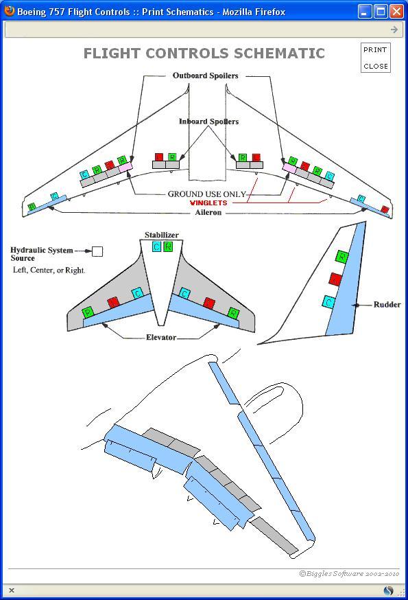
So a guidance rail's sharp edge under its right wing could have made the generator trailer's roof gouge, present on 9/11, and its lower hanging right jet engine could have hit and slit through the two fence corners, if the flight path was indeed 61.2 ° true North, as in the below and above pictures.
But a 60.25 ° true North flight path (so a 1 degree more southernly flight path), as the OS its ASCE report says, is, even further south.
In Google Maps and Google Earth, for example, you can simply click on a location and a pop-up window will give latitude and longitude data to a millionth of a degree.
Impact was at the second floor slab, between the 4th and 5th window, situated to the left of the three long vertical window-indentations , on the west wall, approximately here :
Latitude = 38.87093, Longitude = -77.05834
Lat = 38 degrees, 52.26 minutes North
Long = 77 degrees, 3.50 minutes West
AAL77 its left wing tip would have just missed pole 2 and its right wing tip would have impacted the VDOT camera mast and probably also the northern vertical pole from that overhead traffic signs board, and its right jet engine could have hit the generator trailer its front diesel tank .
Why miss pole 2.? Because in my above picture, my northerly blue line for the plane's left wing tip, which I drew in manually, not with GE its 19 m wing width, is about 1 ° (a few mm) too wide, and then we also have to subtract the width of 1 ° true North, which results in just missing pole 2 :
The 61.2 ° yellow line in the above drawing is the end of the same yellow line as shown in my other picture above this one. And I really tried to pass that right wing tip as close as possible along those 2 obstacles in that 61.2 ° flight path drawing. The vertical poles from the overhead traffic board are in that picture clearly photographed as if in an angle to the ground, so that's why it seems as if I let my blue right wing tip line cut through those two poles. In reality, that line just misses those poles. You just have to blow up the details of that second picture/drawing above (Ctrl and +, seven combined key presses gives the max zoom), to see how I did that.
Its clear that it's easy to be set on the wrong foot by Adam Larson's too real, but undistorted plane, drawn inside that very distorted picture. He should have drawn-in that plane also in a just as distorted version, as seen from the very short angled direction the photographer's position was, at the moment he took this picture, and at that same moment that we now must imagine that the plane came into that scene. That imaginary plane would then be registered in the far above shown Larson picture, in a totally different appearance than Adam drew it in.
new topics
-
Gov Kristi Noem Shot and Killed "Less Than Worthless Dog" and a 'Smelly Goat
2024 Elections: 1 minutes ago -
Falkville Robot-Man
Aliens and UFOs: 15 minutes ago -
James O’Keefe: I have evidence that exposes the CIA, and it’s on camera.
Whistle Blowers and Leaked Documents: 58 minutes ago -
Australian PM says the quiet part out loud - "free speech is a threat to democratic dicourse"...?!
New World Order: 1 hours ago -
Ireland VS Globalists
Social Issues and Civil Unrest: 2 hours ago -
Biden "Happy To Debate Trump"
Mainstream News: 2 hours ago -
RAAF airbase in Roswell, New Mexico is on fire
Aliens and UFOs: 2 hours ago -
What is the white pill?
Philosophy and Metaphysics: 4 hours ago -
Mike Pinder The Moody Blues R.I.P.
Music: 5 hours ago -
Putin, Russia and the Great Architects of the Universe
ATS Skunk Works: 8 hours ago
top topics
-
A Warning to America: 25 Ways the US is Being Destroyed
New World Order: 12 hours ago, 21 flags -
Biden "Happy To Debate Trump"
Mainstream News: 2 hours ago, 7 flags -
Mike Pinder The Moody Blues R.I.P.
Music: 5 hours ago, 7 flags -
What is the white pill?
Philosophy and Metaphysics: 4 hours ago, 5 flags -
Australian PM says the quiet part out loud - "free speech is a threat to democratic dicourse"...?!
New World Order: 1 hours ago, 5 flags -
RAAF airbase in Roswell, New Mexico is on fire
Aliens and UFOs: 2 hours ago, 4 flags -
Putin, Russia and the Great Architects of the Universe
ATS Skunk Works: 8 hours ago, 3 flags -
Ireland VS Globalists
Social Issues and Civil Unrest: 2 hours ago, 3 flags -
James O’Keefe: I have evidence that exposes the CIA, and it’s on camera.
Whistle Blowers and Leaked Documents: 58 minutes ago, 3 flags -
Falkville Robot-Man
Aliens and UFOs: 15 minutes ago, 1 flags
active topics
-
Gov Kristi Noem Shot and Killed "Less Than Worthless Dog" and a 'Smelly Goat
2024 Elections • 0 • : FlyersFan -
Ditching physical money
History • 22 • : StudioNada -
Biden "Happy To Debate Trump"
Mainstream News • 33 • : YourFaceAgain -
Falkville Robot-Man
Aliens and UFOs • 3 • : KKLOCO -
University of Texas Instantly Shuts Down Anti Israel Protests
Education and Media • 296 • : KrustyKrab -
Krystalnacht on today's most elite Universities?
Social Issues and Civil Unrest • 10 • : xuenchen -
Russia Ukraine Update Thread - part 3
World War Three • 5736 • : YourFaceAgain -
Candidate TRUMP Now Has Crazy Judge JUAN MERCHAN After Him - The Stormy Daniels Hush-Money Case.
Political Conspiracies • 794 • : Threadbarer -
Manor Lords - Medieval City Builder with RTS Combat - Early Access 26th April
Video Games • 7 • : gortex -
"We're All Hamas" Heard at Columbia University Protests
Social Issues and Civil Unrest • 289 • : FlyersFan