It looks like you're using an Ad Blocker.
Please white-list or disable AboveTopSecret.com in your ad-blocking tool.
Thank you.
Some features of ATS will be disabled while you continue to use an ad-blocker.

Help A Friend Help A Friend (Measuring Voltage Drop)
page: 11
share:
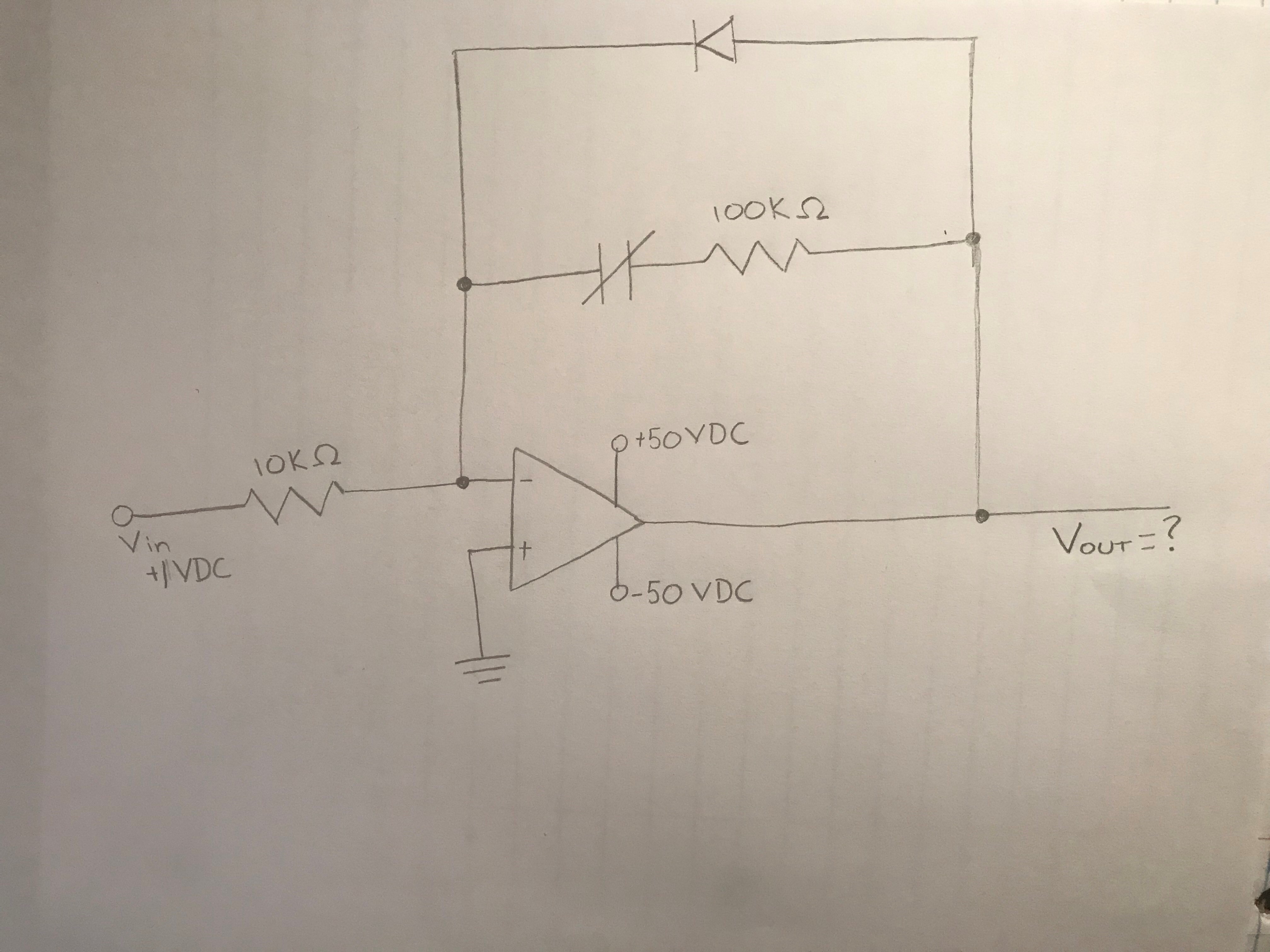
Earlier today I had a friend show me a picture of a simple electrical schematic. He asked me if I remembered how to calculate voltage drops, and I
respond positively. After he showed it to me I discovered I forgot how to figure in amplifiers. So, after about an hour of reeducation I'm getting
pretty frustrated that I still can't figure out what the hell to do.
Can you fine people of ATS take a look at this schematic, and not only tell me what the voltage out is, but how to calculate it? I would really appreciate it.
Can you fine people of ATS take a look at this schematic, and not only tell me what the voltage out is, but how to calculate it? I would really appreciate it.
edit on 20-12-2018 by RealityIsAbsurd because: (no reason given)
a reply to: RealityIsAbsurd
If you have +1v input, then you will have -50v on the output. The capacitor results in a gain of minus infinity.
If you have +1v input, then you will have -50v on the output. The capacitor results in a gain of minus infinity.
originally posted by: graysquirrel
a reply to: RealityIsAbsurd
If you have +1v input, then you will have -50v on the output. The capacitor results in a gain of minus infinity.
I'm pretty sure the OP is looking for the full circuit equation and not just the drop answer.
a reply to: RealityIsAbsurd
If you are talking pure DC, and 'ideal' components, then the cap is pretty much an open circuit and the diode is reverse-biased and so the feedback side across the op-amp (inverting) is not happening, so I'd expect the V-out to go fully to the positive supply rail of the op-amp.
If you are talking pure DC, and 'ideal' components, then the cap is pretty much an open circuit and the diode is reverse-biased and so the feedback side across the op-amp (inverting) is not happening, so I'd expect the V-out to go fully to the positive supply rail of the op-amp.
edit on 21/12/2018 by chr0naut because: (no reason given)
Graysquirrel, my old friend said it's not positive or negative 50VDC. He gave me a hint saying that it wouldn't be any more than positive or negative
10 VDC. I'm currently going over all my calculations again, and will post them so that you all can point out where I'm going astray.
Chr0naut, yeah this is all theoretical in regards to components operating perfectly and all that. You mentioned cap; I take it you mean capacitor? That symbol is for a contact that is normally closed. If there were no line through it that would symbolize a contact that is normally open.
If it were a capacitor the line going through it would be an arrow symbolizing a variable capacitor.
Since it is a normally closed contact it we can disregard it or regard it as a short. It's not a relay with any electromagnetic component.
Am I wrong?
So, there is 1 VDC going across a 10k ohm rated resistor into the negative leg of the amplifier. The amplifier also has a positive and negative 50 VDC
going into it. For the life of me I can't remember how the diode, 100k ohm resistor, and normally closed contact play into the equation. I took a
break from it and watched a movie, but coming back to it I still can't get it. I've forgotten some fundamental.
Ohm's law is V=I*R. So, 1 VDC= (?)I x 10K ohm. So, I=.0001
One can get Power(P) by:
V*I, I squared x R, or V squared / R
I just multiplied the voltage by the amperage and got .0001 for the power.
Therefore, I've got .0001 amperage(power) and voltage going into the amplifier.
You know I think I just mixed up some calculations when I got 10 VDC. I'm fairly certain that it's -10 VDC.
edit on 21-12-2018 by
RealityIsAbsurd because: (no reason given)
a reply to: RealityIsAbsurd
If the capacitor is really a short then the out put will -10v for the +1v input.
If the capacitor is really a short then the out put will -10v for the +1v input.
a reply to: graysquirrel
That's what I'm thinking the Vout is. I guess I got smirked at because I told him that it was positive 10 VDC out instead of -10 VDC.
Ten years ago I wouldn't have had this problem. It's just like all math. If I don't do it everyday my brain tosses it out. I have to reteach myself math about once a year since I don't work with it on a daily basis. I guess I have the gift of modern day computers to thank for that. That's why I get frustrated when I have to actually do the work in my head. Even when I worked with schematics and these kinds of problems in every day work situations troubleshooting was a breeze because I could just take some readings, punch in some values, have a machine do all the brainpower for me and call it a day.
edit on 21-12-2018 by RealityIsAbsurd because: (no reason given)
Yes it's an inverting amplifier with the gain set by the resistors at 10x so the output is -10V
The diode is a red herring in this example and does nothing with the voltages quoted. What it does is clamp the maximum positive output at roughly the forward voltage drop of the diode so dependant on the type (silicom, germanium, shottky). So a typical silicon diode would limit the output to a range of about +0.7V to -50V (negative supply rail) but you can only get a positive output if the Vin is negative.
The diode is a red herring in this example and does nothing with the voltages quoted. What it does is clamp the maximum positive output at roughly the forward voltage drop of the diode so dependant on the type (silicom, germanium, shottky). So a typical silicon diode would limit the output to a range of about +0.7V to -50V (negative supply rail) but you can only get a positive output if the Vin is negative.
edit on 21/12/2018 by
Pilgrum because: (no reason given)
a reply to: Pilgrum
Appreciate it. I thought along the same lines when I told the guy it was 10V. But when he laughed and told me I was wrong it shot me in the foulest of moods. I thought it was pretty ridiculous that I couldn't get something that used to be so simple. So, I guess in my frustration I made it over complicated and started focusing on the wrong things. But every time I did my math I kept getting the same thing over and over. That's when I realized I wasn't inverting it.
Appreciate it. I thought along the same lines when I told the guy it was 10V. But when he laughed and told me I was wrong it shot me in the foulest of moods. I thought it was pretty ridiculous that I couldn't get something that used to be so simple. So, I guess in my frustration I made it over complicated and started focusing on the wrong things. But every time I did my math I kept getting the same thing over and over. That's when I realized I wasn't inverting it.
a reply to: RealityIsAbsurd
The diode has a Vfd. That Vfd will the be same across the 100K resistor and the...cap? If this is strictly DC then Ic +I(100K) is zero. Vout is Vout = Vin + Vfd (inverted); when f = 0. Unless the question is at time = 0, then the cap is a short and this is a 10x inverter. At some frequency the cap has an impedance, Z = 1/wC where w = 2(PI)f.
The diode has a Vfd. That Vfd will the be same across the 100K resistor and the...cap? If this is strictly DC then Ic +I(100K) is zero. Vout is Vout = Vin + Vfd (inverted); when f = 0. Unless the question is at time = 0, then the cap is a short and this is a 10x inverter. At some frequency the cap has an impedance, Z = 1/wC where w = 2(PI)f.
edit on 21-12-2018 by AntiDoppleganger because: (no reason given)
new topics
-
Mike Pinder The Moody Blues R.I.P.
Music: 39 minutes ago -
Putin, Russia and the Great Architects of the Universe
ATS Skunk Works: 3 hours ago -
A Warning to America: 25 Ways the US is Being Destroyed
New World Order: 8 hours ago
top topics
-
President BIDEN's FBI Raided Donald Trump's Florida Home for OBAMA-NORTH KOREA Documents.
Political Conspiracies: 13 hours ago, 31 flags -
A Warning to America: 25 Ways the US is Being Destroyed
New World Order: 8 hours ago, 13 flags -
Is AI Better Than the Hollywood Elite?
Movies: 15 hours ago, 4 flags -
Mike Pinder The Moody Blues R.I.P.
Music: 39 minutes ago, 2 flags -
Maestro Benedetto
Literature: 15 hours ago, 1 flags -
Putin, Russia and the Great Architects of the Universe
ATS Skunk Works: 3 hours ago, 1 flags
active topics
-
Putin, Russia and the Great Architects of the Universe
ATS Skunk Works • 14 • : RussianTroll -
Meadows, Giuliani Among 11 Indicted in Arizona in Latest 2020 Election Subversion Case
Mainstream News • 15 • : IndieA -
Alternate Electors vs Fake Electors - What is the Difference.
2024 Elections • 120 • : Threadbarer -
Gaza Terrorists Attack US Humanitarian Pier During Construction
Middle East Issues • 58 • : matafuchs -
Truth Social goes public, be careful not to lose your money
Mainstream News • 132 • : matafuchs -
New whistleblower Jason Sands speaks on Twitter Spaces last night.
Aliens and UFOs • 67 • : Ophiuchus1 -
Mike Pinder The Moody Blues R.I.P.
Music • 1 • : RussianTroll -
Mood Music Part VI
Music • 3106 • : TheWoker -
University of Texas Instantly Shuts Down Anti Israel Protests
Education and Media • 275 • : Vermilion -
President BIDEN's FBI Raided Donald Trump's Florida Home for OBAMA-NORTH KOREA Documents.
Political Conspiracies • 22 • : 320MPH
1