It looks like you're using an Ad Blocker.
Please white-list or disable AboveTopSecret.com in your ad-blocking tool.
Thank you.
Some features of ATS will be disabled while you continue to use an ad-blocker.

I just made Teslas Free Radiant Energy Device. It Works!
page: 9share:
Originally posted by misterbeefy
Originally posted by misterbeefy
Originally posted by Shirak
Good job. You can increase the voltage by connecting more that one of these in SERIES with each other. You can retain the additional current by connecting some more in PARALLEL to the ones you already have in SERIES. Example:
2 circuits in series produces 14v .1 amp
Create 2 more of these and connect them in series as well for identical results. Now you have 2 circuits producing the said 14v .1 amp EACH.
Now connect the 2 "combined" circuits in parallel. This will give you the same voltage (14v) but DOUBLE your current. Now you have 14v and .2 amp, from a total of 4 of these circuits.
Try it with a total of 6 connected in a 3x3 configuration and you would have 21v and .3amp or 300 mA.
Keep in mind that each circuit would need the same antenna length/diameter, etc.
Another thing to consider is that your typical 12v car battery needs about 15.7 volts being fed to it to be able to charge. You could add some resistors to the circuit in parallel as well to balance out your voltage, while increasing the current.
Hope this helps.
ha ha, he's not going to get more voltage by doubling the circuits.....this isn't the same as a car battery where car batteries have a certain amount STORED in them, this thing is only able to get what it gets out of the air period....
And why wouldn't he? If he built IDENTICAL circuits, placing the antennas side by side, pointing in the same direction, made of the same materieals, etc., then he should obtain the same amount of radiant energy in circuit 2 as he would in circuit 1, thus doubling the voltage. The radiant energy isn't going to suffer a voltage drop just because he has one circuit tuned into it. Listen to your own statement, a car battery has a CERTAIN AMOUNT stored in them, radiant energy doesn't.edit on 17-8-2011 by misterbeefy because: (no reason given)
Friend:
this is why I went with the photovoltaic idea. What I have come into question again and again is the storage issue.
This is what is the latest and greatest....
www.ngk.co.jp...
The answer could just be a hybrid of tech to get there, Tesla, solar, wind, biomass, hydrogen fuel cell....
As someone stated earlier, WE can all figure this out. WE just want to be on the positive side using all WE can vs. going into fossil fuels for the difference!
Regards and Nameste,
Chung-
Originally posted by Shirak
reply to post by Pilgrum
Have you created this circuit yet? Any photos or component list?
I am looking to create a broader spectrum radiant energy meter this circuit looks like it could do the trick.
I made it about 30 years ago from scrap parts and a small home-made printed cct board with the primary use being for detecting microwave leaks and I'm still using it occasionally. The only thing I actually purchased was the Gunn diode and not too sure where you'd get one of those these days, the one I used is a small glass case and looks very similar to a standard 1N4148 or 1N914A silicon diode (but with characteristics like you'd expect in tunnel diodes eg negative resistance region being the most important difference). For experimental purposes the 2 x 220 ohm resistors, 15 ohm resistor, meter and pushbutton switch can all be left out IE all you need is the printed antenna and inductors (the squiggly lines) made to the shown dimensions, the diode and 220pF capacitor to be able to measure a DC voltage from received microwaves across the capacitor. To operate at lower frequencies the antenna needs to get larger in proportion to the average wavelength and the inductors will also need to be larger in terms of inductance having negligible DC resistance.
There's no reason why you couldn't simply bend 2 pieces of bare copper wire to the shown dimensions and glue them down on a piece of cardboard then solder the cap and diode to it. The meter shown was cannibalised from a dead old tape recorder (the VU/battery meter) and it's very sensitive at 250uA full scale. The 15 ohm resistor shunts approx 90% of current away from the meter when the pushbutton switch is closed causing a 10x the voltage scale for reading stronger microwave fields IE any that drive the meter full scale at max sensitivity.
Originally posted by Alxandro
I think circuit that includes a resistor should be omitted from this discussion regarding radiant energy because of the fact that energy that is lost whenever you have resistance in the picture.
Resitors are meant to impede current flow, which in turn dissipates heat, which is essentially lost energy.
Having a resisitor in the circuit is like taking one step back after already taken three steps forward.
There's no implication of anything in the way of 'free energy' in a 'Joule thief' circuit as all it is, is a very simple low power voltage step-up inverter. The basic circuit (without the solar charging additions) really only needs the 2k2 resistor for limiting the transistor base current and the current limiting 1 ohm resistor for protecting the LED can be left out if LED life is of no concern Eg in an application other than one involving driving LEDs. It's practical electronics, not magic
Originally posted by SprocketUK
reply to post by Shirak
Fancy posting up the schematic you used?
I feel like playing with a soldering iron for a while...edit on 15-8-2011 by SprocketUK because: I'm a spaz
edit on 22-8-2011 by Fromabove because: (no reason given)
Voltage without amperage means very little. Most metals will pick up a certain amount of energy and show it as voltage, but when you attempt to use it
it disappears.
reply to post by Fromabove
The cause of that effect is impedance. A high impedance source can show a high voltage as long as you use a higher impedance instrument to measure it and modern digital multimeters can have an impedance of 10 megohms or more on voltage scales while older moving coil type analog meters have a much much lower impedance which can result in a virtual zero reading from the same high impedance source that gave a substantial reading using the digital meter.
The cause of that effect is impedance. A high impedance source can show a high voltage as long as you use a higher impedance instrument to measure it and modern digital multimeters can have an impedance of 10 megohms or more on voltage scales while older moving coil type analog meters have a much much lower impedance which can result in a virtual zero reading from the same high impedance source that gave a substantial reading using the digital meter.
Originally posted by Fromabove
Voltage without amperage means very little. Most metals will pick up a certain amount of energy and show it as voltage, but when you attempt to use it it disappears.
Yes this is why several times in this thread I have shown that the circuit has current.. Also I found hooking two circuits in parallel with separate antennas doubled the current output.
Originally posted by Shirak
Originally posted by Fromabove
Voltage without amperage means very little. Most metals will pick up a certain amount of energy and show it as voltage, but when you attempt to use it it disappears.
Yes this is why several times in this thread I have shown that the circuit has current.. Also I found hooking two circuits in parallel with separate antennas doubled the current output.
you guys are still talking about tiny milliamps, even tesla had to use the electricity from the utility grid to run his 300 ft lightning tower....
Originally posted by Shirak
Originally posted by Fromabove
Voltage without amperage means very little. Most metals will pick up a certain amount of energy and show it as voltage, but when you attempt to use it it disappears.
Yes this is why several times in this thread I have shown that the circuit has current.. Also I found hooking two circuits in parallel with separate antennas doubled the current output.
what were you using as a load?
Originally posted by patternfinder
Originally posted by Shirak
Originally posted by Fromabove
Voltage without amperage means very little. Most metals will pick up a certain amount of energy and show it as voltage, but when you attempt to use it it disappears.
Yes this is why several times in this thread I have shown that the circuit has current.. Also I found hooking two circuits in parallel with separate antennas doubled the current output.
what were you using as a load?
Already posted on the previous page
I did a little experiment myself and yes, there's definitely a tiny amount of energy to be 'collected' even in relatively quiet places (in terms of EM
fields) such as where I live. Sincere condolences to any who forked out the money for the 1N34, OA47 or other Germanium diodes which are insanely
expensive these days and my earlier recommendation to use schottky types instead still stands. For my experiment I simply used what I had on hand
which were the ubiquitous and very cheap 1N4004 standard silicon 400V 1A diodes and they worked well indeed.
For a price comparison I checked with my usual bulk supplier & got the following figures:
Germanium diodes (OA47, 1N34) cost around $3-4 each in small quantities
Comparable Schottky diodes of similar or better ratings (eg BAT41 or 1N5819) are about $10 per 100
1N4004 can be had for less than $0.10 each or even around 2c each by the reel of 5000
Assembled bridges of similar rating (eg W02) are less than $1 each which means this little experiment can easily be done for about $1.
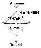
It's just a bridge rectifier with an antenna and the ground is a metal rod hammered into moist ground. The antenna, well the bigger the better and it can be any single conductor like that thin galvanised steel wire the hardware sells in rolls (cheap) - just run it along the top of a timber fence or string between trees or whatever. The output -/+ need to be kept isolated from the ground (otherwise you're just shorting out half of the bridge). The charge accumulates on the electrolytic cap and some may observe that I used a lower voltage rating cap in relation to the diodes. The best possible outcome of this would be the cap exploding :O and that would be the equivalent of striking oil (time to upscale) but obviously my optimism was low being the realist I am.
Don't expect to get anything significant from it apart from some learning although some may be in areas better than others for this experiment. I'd consider my location to be among the worst and it works here if only just.
For a price comparison I checked with my usual bulk supplier & got the following figures:
Germanium diodes (OA47, 1N34) cost around $3-4 each in small quantities
Comparable Schottky diodes of similar or better ratings (eg BAT41 or 1N5819) are about $10 per 100
1N4004 can be had for less than $0.10 each or even around 2c each by the reel of 5000
Assembled bridges of similar rating (eg W02) are less than $1 each which means this little experiment can easily be done for about $1.
It's just a bridge rectifier with an antenna and the ground is a metal rod hammered into moist ground. The antenna, well the bigger the better and it can be any single conductor like that thin galvanised steel wire the hardware sells in rolls (cheap) - just run it along the top of a timber fence or string between trees or whatever. The output -/+ need to be kept isolated from the ground (otherwise you're just shorting out half of the bridge). The charge accumulates on the electrolytic cap and some may observe that I used a lower voltage rating cap in relation to the diodes. The best possible outcome of this would be the cap exploding :O and that would be the equivalent of striking oil (time to upscale) but obviously my optimism was low being the realist I am.
Don't expect to get anything significant from it apart from some learning although some may be in areas better than others for this experiment. I'd consider my location to be among the worst and it works here if only just.
edit on 28/8/2011 by Pilgrum because: enhanced grammatical
consistency
As promised here is my reply to those who postulated that the Tesla Radiant energy circuit could not handle a load. My led's came in the mail
yesterday AVO.
I maintain that personal experimentation is the best way to deconstruct disinformation. Yes as demonstrated here the circuit can handle a load connected in two different configurations.
Enjoy
I maintain that personal experimentation is the best way to deconstruct disinformation. Yes as demonstrated here the circuit can handle a load connected in two different configurations.
Enjoy
The ultimate end is to take captured charges in the capacitor and
store in a battery. I heard of this years ago on the net in a gold
forum as some one used a line antenna and capacitor to charge
a battery. This type of charge recovery was patented by Tesla
with his usual ground connection for the capacitor.
Parallel capacitor connections increases the capacitance.
Here is a patented way Tesla use to charge a battery.
He focused rays upon an insulated plate that knock out
charges causing the capacitor to react. The beam focus
was a solid metal hemisphere:
www.google.com...
I always wondered how effective the method worked.
I thought of using ball bearings but looks like some are ready
made. The beam focus is used by Tesla on some of his
other devices.
Originally posted by TeslaandLyne
The ultimate end is to take captured charges in the capacitor and
store in a battery. I heard of this years ago on the net in a gold
forum as some one used a line antenna and capacitor to charge
a battery. This type of charge recovery was patented by Tesla
with his usual ground connection for the capacitor.
Parallel capacitor connections increases the capacitance.
Here is a patented way Tesla use to charge a battery.
He focused rays upon an insulated plate that knock out
charges causing the capacitor to react. The beam focus
was a solid metal hemisphere:
www.google.com...
I always wondered how effective the method worked.
I thought of using ball bearings but looks like some are ready
made. The beam focus is used by Tesla on some of his
other devices.
Thanks for the link I will see how I can implement this into my design. I found as a bonus last night the circuit can be used to absorb excess local radiant energy ie that caused by cell phone towers HV power lines and transformers. I will try and record the experiment that proves it and post it here.
edit on 31-8-2011 by Shirak because: extra
Originally posted by Shirak
So after hearing about this and watching a video on it I wanted to test the design for myself.
My Shopping list.
Shopping list.
4 - Germanium Diodes (1N34)
2 - 100 uF 50V electrolytic Capacitors
2- 0.2 uF 50V ceramic capacitors
Antenna or wire.
I bought extra and bought it all on ebay it was less than 3 dollars for mats for one and I didn't pay freight so win.
anyhoo.
I tested it outdoors near dusk.
I then tested it indoors near a radiant energy source.
The output was 7.07 Volt DC and 0.10 amp.
Anyways made two of these circuits and was wondering if anyone could give me some advice as to what the best way to connect the two in parallel is I am hoping to increase my outdoor output by using more antenna arrays.
edit on 15-8-2011 by Shirak because: Spelling
HI all great thread ! my son is doing an 7th grade science fair project to vary the length of the antenae and record the results. I don't know much about electronics can anyone show me how to actually make the connections? He has all the parts. I would really appreciate it.
Does this setup look correct? Any help would be appreciated


edit on 7-1-2013 by ScienceFair because: smaller image
edit on 7-1-2013 by ScienceFair because: resize the image to make it
viewable
The circuit looks a bit different. I have posted a how to make one
www.youtube.com...[editb y]edit on 15-1-2013 by Shirak because: Add link
www.youtube.com...[editb y]edit on 15-1-2013 by Shirak because: Add link
Just curious in your second Video when your doing the amp test did you have one probe in each of the terminals on the 9v connector?
Brilliant thread glad you guys bumped it with your continued discussion.
Very cool, this is why I love ats, education
Haven't read the entire thing yet but theat vid of Grebennikov's flying platform was crazy!
Never heard of that before.
Very cool, this is why I love ats, education
Haven't read the entire thing yet but theat vid of Grebennikov's flying platform was crazy!
Never heard of that before.