It looks like you're using an Ad Blocker.
Please white-list or disable AboveTopSecret.com in your ad-blocking tool.
Thank you.
Some features of ATS will be disabled while you continue to use an ad-blocker.

WTC towers construction
page: 10
share:
Ok....this might be the wrong section. I thought of putting this thread in the research section. If this is the wrong section please
move....thanks.
Anyway, here is what I am proposing. I know there are a lot of people here who have contributed to the 9/11 threads and have spent a great deal researching this topic. I am trying to piece together the construction of the WTC buildings 1, 2 and 7 to do more of a structural analysis than can be done just from what NIST and FEMA have listed.
So, I'm asking all of you to help me put the pieces together to maybe be able to draw the building and at least most of it's components. Any info or links to get us started would be great. This will take some time but if we all work together, I think we might be able to come up with some kind of working drawings.
This is NOT the thread to debate this and that about how they fell....just how they were constructed....thanks.
Originally posted by MacMerdin
This is NOT the thread to debate this and that about how they fell....just how they were constructed....thanks.
~~~~~~~~~~~~~~~~~~~~~~~~~~~~~~~~~~~~~~~~~~~
i doubt if anything has changed since this 'Guardian' article was published, ....; 911research.wtc7.net...
(in red lettering) "...The good people who held the plans and blueprints
for the WTC buildings, wishing to help in any way they could,
refused to make the bulk of them available to anyone who might understand them..."
-------------------
Perhaps someone could access originals or copies of the plans & specs,
which were required to be issued a permit, for the groundbreaking and
construction....
-- the WTC complex started 5 August 1966
-- steel erection for Tower #1 began in August 1968
-- occupancy for Tower #1 was in December 1970
-- occupancy for Tower #2 was in January 1972
you might also try the DDC [NYC Dept of Design & Construction]
Port Authority of NYC
or other Structural Engineering entities you might find,
if you scroll down & review sections:
1.5.1. Building Codes (in the link provided)
1.5.2. Unusual Building Loads (ditto)
------------------------------------
good luck
The majority of the plans were probably lost in the collapse. The NIST appendices do contain a number of design criteria documents. The framing
plans per floor are available, since the core areas didn’t change from floor to floor (with the exception of the mechanical areas and sky lobbies),
the typical framing plan is applicable for the whole building. I believe that the core column schedule is in there somewhere also, if not in a
diagram, there is some narrative description of the different steel strength specifications. The key is the bolted connections. There is a good deal
of info on the truss connection to the exterior walls, and the exterior column splices, I’m not sure if there is much in their on the specific core
column connections. You may be able to figure it out from the photographs.
My problem with NIST is so far all I have seen from their diagrams is pictures....no details as far as dimensions of anything. Yes, they have a floor
plan, but could anyone draw on AutoCad what they are describing? I would say no because there isn't enough dimensions to do the job justice.
As far as the inner core....I have been looking into it and there are basically three different types of WF columns. They show that the corners (columns 1001, 1008, 501, 508) were W14x730, that 2 columns (columns 607, 906) were W14x219, and that column 705 was W14x61. What about the other columns? They have described 7 out of 47 columns. In the diagrams, you can't even go by the thickness of line types to differenciate which columns were what.
I haven't tried to contact the Port Authority as of yet. What should I tell them what my reason is for wanting the drawings?
I never thought about the drawings being destroyed because of the fall. Still, there would have to be backups of the drawings....i.e. the designers themselves would have copies....at least I know we keep copies of our designs.
Originally posted by MacMerdin
I haven't tried to contact the Port Authority as of yet. What should I tell them what my reason is for wanting the drawings?
Still, there would have to be backups of the drawings....i.e. the designers themselves would have copies....at least I know we keep copies
maybe your building a meticulous scale model....???
and a cross-section
2 storie walk-thru mockup, for interactive tours of the crash experience
yes, the Architects & Designers & Insurers & underwriters & Structural Steel Engineers & then there's the the elevator people, electricians et al....all these trades
would have different sets of plans with Details....it would be quite a task but one could potentially find the specs & plans which 'they" are refusing to make available to the public.
Originally posted by MacMerdin
I haven't tried to contact the Port Authority as of yet. What should I tell them what my reason is for wanting the drawings?
I don't think it would really matter. I've contacted a major demolition company, and gave them a very good, verifiable (albeit false) reason for wanting information regarding exactly what technology they have at their disposal when it comes to actually demolishing buildings, and they wouldn't even tell me anything. They even referenced national security as a reason for their being fishy with me. Now I wonder what exactly they're protecting citizens from by withholding that information. But I digress...
You can find some information here, but you may already know all of it. Maybe it would help if you asked for us to look for specific information?
The cores were rectangular pillars with numerous large columns and girders, measuring 87 feet by 133 feet. ...
Reports on the number of core columns vary from 44 to 47. The exact arrangement of the columns is not known due to the secrecy of detailed engineering drawings of the towers. It is clear from photographs, such as the one on the right, that the core columns were abundantly cross-braced.
Establishing the true nature of the core structures is of great importance given that the most widely read document on the World Trade Center attack -- the 9/11 Commission Report -- denies their very existence, claiming the towers' cores were "hollow steel shaft[s]:" ...
The core columns were steel box-columns that were continuous for their entire height, going from their bedrock anchors in the sub-basements to near the towers' tops, where they transitioned to H-beams. Apparently the box columns, over 1000 feet long, were built as the towers rose by welding together sections several stories long. The sections were fabricated by mills in Japan that were uniquely equipped to produce the large pieces. 2
Some of the core columns apparently had outside dimensions of 36 inches by 16 inches. Others had larger dimensions, measuring 52 inches by 22 inches. 3 The core columns were oriented so that their longer dimensions were perpendicular to the core structures' longer, 133-foot-wide sides. Construction photographs found at the Skyscraper Museum in New York City indicate that the outermost rows of core columns on the cores' longer sides were of the larger dimensions. Both the FEMA's World Trade Center Building Performance Study and the NIST's Draft Report on the Twin Towers fail to disclose the dimensions of the core columns, and the NIST Report implies that only the four core columns on each core's corners had larger dimensions.
Possibly a typical core column:
Column base:
Perimeter columns:
Floors:
Hat trusses:
According to NIST:
There's more on the link, which again is here. Like I said, you probably already have all of this stuff. The site makes an important note of the fact that we can't be sure how the core was arranged, and even FEMA's report seems to contradict itself on the arrangement of core columns.
here is a link you might find useful. haven't looked at everything there, but maybe some links can be found once you get to the sight....
skyscraper page
let me know if this helps
skyscraper page
let me know if this helps
It's probably not what you are looking for, but some good info, none the less:
www.icivilengineer.com...
scott-juris.blogspot.com...
scott-juris.blogspot.com...
www.icivilengineer.com...
scott-juris.blogspot.com...
scott-juris.blogspot.com...
this is from the fema report:
interestingly, from that report we learn that, the core box columns were in ONE CONTINUOUS PIECE. welded together all the way up.
The WTC towers, also known as WTC 1 and WTC 2, were the primary components of the sevenbuilding World Trade Center complex. Each of the towers encompassed 110 stories above the Plaza level and seven levels below. WTC 1 (the north tower) had a roof height of 1,368 feet, briefly earning it the title of the world’s tallest building. WTC 2 (the south tower) was nearly as tall, with a roof height of 1,362 feet. WTC 1 also supported a 360-foot-tall television and radio transmission tower. Each building had a square floor plate, 207 feet 2 inches long on each side. Corners were chamfered 6 feet 11 inches. Nearly an acre of floor space was provided at each level. A rectangular service core, with overall dimensions of approximately 87 feet by 137 feet, was present at the center of each building, housing 3 exit stairways, 99 elevators, and 16 escalators.
interestingly, from that report we learn that, the core box columns were in ONE CONTINUOUS PIECE. welded together all the way up.
The buildings’ signature architectural design feature was the vertical fenestration, the predominant element of which was a series of closely spaced built-up box columns. At typical floors, a total of 59 of these perimeter columns were present along each of the flat faces of the building. These columns were built up by welding four plates together to form an approximately 14-inch square section, spaced at 3 feet 4 inches on center. Adjacent perimeter columns were interconnected at each floor level by deep spandrel plates, typically 52 inches in depth. In alternate stories, an additional column was present at the center of each of the chamfered building corners. The resulting configuration of closely spaced columns and deep spandrels created a perforated steel bearing-wall frame system that extended continuously around the building perimeter.
Figure 2-3 presents a partial elevation of this exterior wall at typical building floors. Construction of the perimeter-wall frame made extensive use of modular shop prefabrication. In general, each exterior wall module consisted of three columns, three stories tall, interconnected by the spandrel plates, using all-welded construction. Cap plates were provided at the tops and bottoms of each column, to permit bolted connection to the modules above and below. Access holes were provided at the inside face of the columns for attaching high-strength bolted connections. Connection strength varied throughout the building, ranging from four bolts at upper stories to six bolts at lower stories. Near the building base, supplemental welds were also utilized. Side joints of adjacent modules consisted of high-strength bolted shear connections between the spandrels at mid-span. Except at the base of the structures and at mechanical floors, horizontal splices between modules were staggered in elevation so that not more than one third of the units were spliced in any one story. Where the units were all spliced at a common level, supplemental welds were used to improve the strength of these connections. Figure 2-3 illustrates the construction of typical modules and their interconnection. At the building base, adjacent sets of three columns tapered to form a single massive column, in a fork-like formation,
shown in Figure 2-4.
Twelve grades of steel, having yield strengths varying between 42 kips per square inch (ksi) and 100 ksi, were used to fabricate the perimeter column and spandrel plates as dictated by the computed gravity and wind demands. Plate thickness also varied, both vertically and around the building perimeter, to accommodate the predicted loads and minimize differential shortening of columns across the floor plate. In upper stories of the building, plate thickness in the exterior wall was generally 1/4 inch. At the base of the building, column plates as thick as 4 inches were used. Arrangement of member types (grade and thickness) was neither exactly symmetrical within a given building nor the same in the two towers.
The stiffness of the spandrel plates, created by the combined effects of the short spans and significant depth, created a structural system that was stiff both laterally and vertically. Under the effects of lateral wind loading, the buildings essentially behaved as cantilevered hollow structural tubes with perforated walls. In each building, the windward wall acted as a tension flange for the tube while the leeward wall acted as a compression flange. The side walls acted as the webs of the tube, and transferred shear between the windward and leeward walls through Vierendeel action (Figure 2-5). Vierendeel action occurs in rigid trusses that do not have diagonals. In such structures, stiffness is achieved through the flexural (bending) strength of the connected members. In the lower seven stories of the towers, where there were fewer columns (Figure 2-4), vertical diagonal braces were in place at the building cores to provide this stiffness. This structural frame was considered to constitute a tubular system.
Floor construction typically consisted of 4 inches of lightweight concrete on 1-1/2-inch, 22-gauge non-composite steel deck. In the core area, slab thickness was 5 inches. Outside the central core, the floor deck was supported by a series of composite floor trusses that spanned between the central core and exterior wall. Composite behavior with the floor slab was achieved by extending the truss diagonals above the top chord so that they would act much like shear studs, as shown in Figure 2-6. Detailing of these trusses was similar to that employed in open-web joist fabrication and, in fact, the trusses were manufactured by a joist fabricator, the LaClede Steel Corporation. However, the floor system design was not typical of open-web-joist floor systems. It was considerably more redundant and was well braced with transverse members. Trusses were placed in pairs, with a spacing of 6 feet 8 inches and spans of approximately 60 feet to the sides and 35 feet at the ends of the central core. Metal deck spanned parallel to the main trusses and was directly supported by continuous transverse bridging trusses spaced at 13 feet 4 inches and intermediate deck support angles spaced at 6 feet 8 inches from the transverse trusses. The combination of main trusses, transverse trusses, and deck support enabled the floor system to act as a grillage to distribute load to the various columns.
Thanks everyone. I think there is enough info to get me started. I think I can actually maybe get started on a typical floor plan....we'll see.
Again...thanks..I'll post anything I find also.
I just recieved this response in an engineering forum I belong to. I hope that posting this reply doesn't go against any ATS rules. I have not
included who or where this post is from, so I think I'm in the limits of the rules.....if not, can a mod delete this post...or let me know so I can
edit it. Thanks.
So, I googled and found an interesting site.
www.skyscraper.org...
I will probably be going to NYC sometime soon....we have an office there. So, I'm definately going to check this out.
[edit on 6-12-2005 by MacMerdin]
Mac- Fyi copies of a portion of the original construction docs (Floor plans and sections)for the WTC were displayed in public in an outdoor exhibition in NYC about five or six months after the attacks. Sorry I don't remember the exact name of the exhibit or the organizer, but I viewed it personally, briefly. The drawings were dated 1968 or '69. Try contacting the city DBC or googling for old data on exhibits on the WTC in the NYC metro area.
So, I googled and found an interesting site.
www.skyscraper.org...
I will probably be going to NYC sometime soon....we have an office there. So, I'm definately going to check this out.
[edit on 6-12-2005 by MacMerdin]
I just recieved this reply post also on the same forum. This is getting interesting. Haven't googled it yet...was too exited...we'll see if I can
come up with anything.
The structural portion of the design drawings were also part of a buildings exhibit at the MOMA (Museum of Modern Art) in New York City about 2 years ago. They were in book form and had all the floor plans and elevations with all structural members clearly identified. The Structural Engineer, Leslie Robertson, had his name & PE stamp on them.
Ok...I've been trying to draw a typical floor-framing plan on AutoCad...like the one in NIST. Well, lets just say that the dimensions that NIST has
been giving are totally wrong. Nothing fits the way they say. I know some of their dimensions are rounded either up or down but come-on.....a lot of
it isn't even close. Wish I could get some real answers.
have you searched of anyone who has done the same thing your trying to do or is attempting.
would've thought this would be something someone has already tried their hand on to replicate the towers and test the damage themselves.
keep us posted.
would've thought this would be something someone has already tried their hand on to replicate the towers and test the damage themselves.
keep us posted.
Well, I guess drawing things to scale is beyond NIST. I just scanned their image of a typical floor plan and inserted it into AutoCad and scaled it
to fit one side being 207 feet and 2 inches.....guess what.....nothing else fits. This is just getting to be more and more fishy. For example...the
chamfer at the corners becomes 8.5 feet instead of the stated 6 feet 11 inches. Jeez...you would think that engineers could handle drawing a sketch
to scale.
In their defense...it doesn't say that it is a scaled drawing. It's just that, why would they produce a sketch without scaling it? I'm confused....did they think we don't deserve an actual sketch of a typical floor or what?
All I have to say to NIST......poor job guys.
In their defense...it doesn't say that it is a scaled drawing. It's just that, why would they produce a sketch without scaling it? I'm confused....did they think we don't deserve an actual sketch of a typical floor or what?
All I have to say to NIST......poor job guys.
here's some more info on the towers
Multi-Storey Buildings in Steel, Godfrey, GB (Editor); Second Edition; Collins, London, England, 1985
References
Architectural Forum, 4/1 964. p. 119.
Engineering News-Record. 9/1964. p. 36; 11/1971.
Der Stahlbau, 11/1964. p. 350; 4/1970. p. 123.
Der Baningenleur. 9/1965. p.373:11/1967, p. 421.
Bauwelt. 32/1 966. p. 909.
Acier-Stahl-Steel. 12/1966, p. 556:6/1970. p. 273.
Originally posted by MacMerdin
Well, I guess drawing things to scale is beyond NIST. I just scanned their image of a typical floor plan and inserted it into AutoCad and scaled it to fit one side being 207 feet and 2 inches.....guess what.....nothing else fits. This is just getting to be more and more fishy. For example...the chamfer at the corners becomes 8.5 feet instead of the stated 6 feet 11 inches. Jeez...you would think that engineers could handle drawing a sketch to scale.
In their defense...it doesn't say that it is a scaled drawing. It's just that, why would they produce a sketch without scaling it? I'm confused....did they think we don't deserve an actual sketch of a typical floor or what?
All I have to say to NIST......poor job guys.
I just did the same thing. I took Figure 2-14 (typical framing plan) from the draft report and copied it out as a TIFF image. I scaled it upwards by a factor of 420 or so. (you have to re-scale it a couple of times to insure accuracy).
I then drew a 207’-2” (2486”) square and then drew two smaller lines 6’-11” (83”) down and over from the top left corner. I then drew a line across from the ends of these two lines to form the chamfer. I overlaid this on the background image.
It fit perfectly.
Are you sure you are measuring the right lines? The chamfer is measured in the distance in from the corner, not the distance across (i.e. the legs of the triangle, not the hypotenuse). The distance across, as I’ve measured it is 9’ -9 7/16” , Which is closer to the dimension that you have come up with.

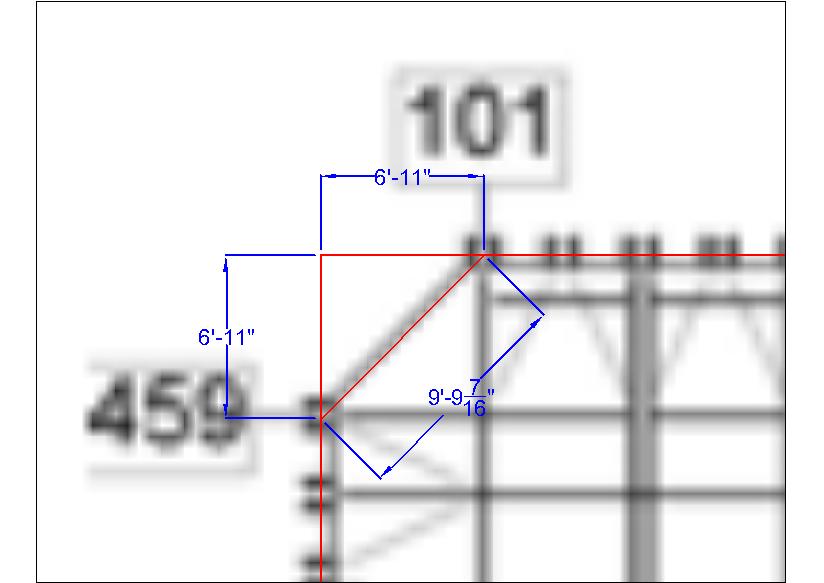
[edit on 27-12-2005 by HowardRoark]
new topics
-
BIDEN Admin Begins Planning For January 2025 Transition to a New President - Today is 4.26.2024.
2024 Elections: 2 hours ago -
Big Storms
Fragile Earth: 4 hours ago -
Where should Trump hold his next rally
2024 Elections: 6 hours ago -
Shocking Number of Voters are Open to Committing Election Fraud
US Political Madness: 7 hours ago -
Gov Kristi Noem Shot and Killed "Less Than Worthless Dog" and a 'Smelly Goat
2024 Elections: 8 hours ago -
Falkville Robot-Man
Aliens and UFOs: 8 hours ago -
James O’Keefe: I have evidence that exposes the CIA, and it’s on camera.
Whistle Blowers and Leaked Documents: 9 hours ago -
Australian PM says the quiet part out loud - "free speech is a threat to democratic dicourse"...?!
New World Order: 10 hours ago -
Ireland VS Globalists
Social Issues and Civil Unrest: 10 hours ago -
Biden "Happy To Debate Trump"
2024 Elections: 11 hours ago
top topics
-
James O’Keefe: I have evidence that exposes the CIA, and it’s on camera.
Whistle Blowers and Leaked Documents: 9 hours ago, 17 flags -
Australian PM says the quiet part out loud - "free speech is a threat to democratic dicourse"...?!
New World Order: 10 hours ago, 15 flags -
Blast from the past: ATS Review Podcast, 2006: With All Three Amigos
Member PODcasts: 13 hours ago, 13 flags -
Biden "Happy To Debate Trump"
2024 Elections: 11 hours ago, 13 flags -
Ireland VS Globalists
Social Issues and Civil Unrest: 10 hours ago, 9 flags -
Mike Pinder The Moody Blues R.I.P.
Music: 13 hours ago, 8 flags -
Shocking Number of Voters are Open to Committing Election Fraud
US Political Madness: 7 hours ago, 6 flags -
BIDEN Admin Begins Planning For January 2025 Transition to a New President - Today is 4.26.2024.
2024 Elections: 2 hours ago, 6 flags -
What is the white pill?
Philosophy and Metaphysics: 12 hours ago, 6 flags -
RAAF airbase in Roswell, New Mexico is on fire
Aliens and UFOs: 11 hours ago, 5 flags
active topics
-
RAAF airbase in Roswell, New Mexico is on fire
Aliens and UFOs • 12 • : pianopraze -
BIDEN Admin Begins Planning For January 2025 Transition to a New President - Today is 4.26.2024.
2024 Elections • 14 • : WeMustCare -
A Warning to America: 25 Ways the US is Being Destroyed
New World Order • 29 • : 19Bones79 -
Big Storms
Fragile Earth • 15 • : Caver78 -
What is the white pill?
Philosophy and Metaphysics • 22 • : AlexandrosOMegas -
University of Texas Instantly Shuts Down Anti Israel Protests
Education and Media • 315 • : CriticalStinker -
Gov Kristi Noem Shot and Killed "Less Than Worthless Dog" and a 'Smelly Goat
2024 Elections • 58 • : cherokeetroy -
Biden "Happy To Debate Trump"
2024 Elections • 51 • : rickymouse -
Hate makes for strange bedfellows
US Political Madness • 53 • : 19Bones79 -
SETI chief says US has no evidence for alien technology. 'And we never have'
Aliens and UFOs • 79 • : SchrodingersRat
0