It looks like you're using an Ad Blocker.
Please white-list or disable AboveTopSecret.com in your ad-blocking tool.
Thank you.
Some features of ATS will be disabled while you continue to use an ad-blocker.

Looking for help building a circuit for a car project (electronic wizzard needed)
page: 12
share:
Okay so I need to set some inputs on a free programmable ECU externally. Many do that with mechanical switches and it's a no brainer. But I need to
do it electronic from an Arduino to integrate some fancy stuff that can not be done by the ECU. I need to have something in between "translating"
the voltage, because Arduino gives out 5V but the ECU expects something in between 11-13.8V.
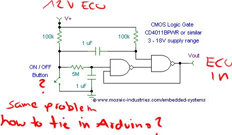
I thought the most simple way is to use this 8 channel relay module. But it has one caveat, it will turn on all relay by standard whenever the board is being powered on. This is not acceptable.
Because all 8 channels will turn on and I have to turn them back off programmatically. That leads to these 8 channels being HIGH for a short time on the ECU side whenever it boots up. And I saw that I also have a bouncing problem and debouncing on ECU side is difficult to impossible. Then also I do not know if the relay can take forces in the range of 2G or vibrations.
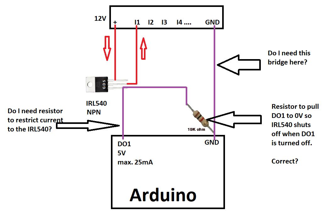
So I found a similar circuit for switching on a motor and modified it to what I need. Can someone with electronic knowledge tell me if that works? From the ECU side it should look like a switch. I am unsure about these three things, because I do not want to kill the ECU inputs (or worse).
1) Do I need the GND bridge?
2) Do I need a resistor between the Arduino and the Gate?
3) The 10k resistor I think is needed for making the gate turn off and not stay on forever after arduino digital output is 0V again? Right?
I calculated it will only shave off 0.5mA from the arduino, it can maximum do 25mA.
I am not registered on any such boards and I do not want to register just for asking the question. I know people dislike such a MO. So I thought before getting these people on the German board snappy and riled up (they really seem to be condescending towards new people), I thought I ask my beloved ATS friends for help first.
Here is the datasheetfor IRL540
I thought the most simple way is to use this 8 channel relay module. But it has one caveat, it will turn on all relay by standard whenever the board is being powered on. This is not acceptable.
Because all 8 channels will turn on and I have to turn them back off programmatically. That leads to these 8 channels being HIGH for a short time on the ECU side whenever it boots up. And I saw that I also have a bouncing problem and debouncing on ECU side is difficult to impossible. Then also I do not know if the relay can take forces in the range of 2G or vibrations.
So I found a similar circuit for switching on a motor and modified it to what I need. Can someone with electronic knowledge tell me if that works? From the ECU side it should look like a switch. I am unsure about these three things, because I do not want to kill the ECU inputs (or worse).
1) Do I need the GND bridge?
2) Do I need a resistor between the Arduino and the Gate?
3) The 10k resistor I think is needed for making the gate turn off and not stay on forever after arduino digital output is 0V again? Right?
I calculated it will only shave off 0.5mA from the arduino, it can maximum do 25mA.
I am not registered on any such boards and I do not want to register just for asking the question. I know people dislike such a MO. So I thought before getting these people on the German board snappy and riled up (they really seem to be condescending towards new people), I thought I ask my beloved ATS friends for help first.
Here is the datasheetfor IRL540
You are looking to switch a 12v source for an input to the ecu? But you need to do it with an external device like an Arduino.
Why don't you use the 5v output from the pins of the Arduino to a 5v relay? That is what this little guy is for.
www.amazon.com...
You still get the programmable control of the Arduino and the ability to switch a lot more current. I don't know what your requirements are as far as the input of the ecu.
Is this just a way to switch a function on the ecu via an intermediary device?
Your schematic looks good, you shouldn't need the ground you have drawn as the ecu has a ground built in. The resistor will add extra load to the output on the Arduino and may put you over your limit on that devices gpio pins. Though I know you need it to unlatch the gate.
You could get around the resistor by making a dual mosfet latching device and use the output of the Arduino as switch input of the latching device. Then you would make the output of the Arduino pulse once for on and once for off in place of the momentary switch.
Also I would put a small fuse in the 12v source line before the mosfet. something like a .5 amp, read that as 1/2 amp. This way you don't overdraw from the ecu and fry it.
This would be easier to setup with the relay I linked instead of the mosfet. You just need to remove the resistor and add a ground for the relay and you got it.
It would be easier to help if I knew what you were trying to control.
a reply to: shaneslaughta
I did. I have that version but in 8channel. The problem is, when the board get's powered on for the first time, the relay go active and I can not prevent this. This means when the ignition is turned on and the 12V to 5V DC-DC power supply is energized and powers up the arduino, the relay will be energized and the ECU get's HIGHs on all inputs. I can choose between NO and NC of course but that does not help me, as it goes into that state.
So if the relay board is "alive" after the ECU initialized, what is the case, all 8 inputs connected to the relay board are set HIGH. I tried to disable the relay programmatically by writing a 0 to all the pins when the Arduino boots. I also messed with Arduino internal pullup and pulldown modes but the relay does that by itself.
I asked someone on discord because I saw that 8 channel relay and used the opportunity to ask. But my relay are not faulty, it does that by default. I could solve it by having a manual switch in the car using an input on the ECU and set a variable so it ignores the inputs until the switch is flicked, but kind of defeats the purpose and means a lot of extra work and would spaghetti the code inside the ECU, that I want to keep clean, because cycle time.
Kind of. It's more complicated. I communicate via CANBUS with the ECU to have a feedback loop to the arduino but it only works ECU to Arduino, not the other way around. I can not handle the busmessages from the Arduino and I know out of experience when the ignition system is going full load @9k RPM that the EM interference brings noise onto the CANBUS and gobble things up.
The arduino manages a few functions the ECU can not. For example I have a dry ice reservoir for the water intercooler. With the push of a button I can inject dry ice pellets into it, gravity fed. Or that's the plan. It will drop the intake temperatures and allows me to inject more fuel into the cylinders without getting too rich. At the same time, when that happens, I need the ECU to disable some safety features and change some fields in the fuel map plus features. Because I also run overboost button on the steering wheel, I need to consider that state too.
Then when the ECU tells the arduino via CANBUS that the exhaust manifold is approaching a certain temperature that it does not inject the pellets anymore. For that the ECU has to talk to the Arduino. But I can not craft messages on the Arduino that the ECU accepts.
A few other wild things happen that have to do with exhaust back pressure I utilize to get even more compression into the cylinders. So I have different modes in the ECU and net to interlock it with the Arduino.
I added fuses to the circuit, that's a good idea. The ECU has a fuse already but if I use super fast fuses they should burn before the ECU fuse does. It's a slow fuse inside the ECU.
Why don't you use the 5v output from the pins of the Arduino to a 5v relay? That is what this little guy is for.
I did. I have that version but in 8channel. The problem is, when the board get's powered on for the first time, the relay go active and I can not prevent this. This means when the ignition is turned on and the 12V to 5V DC-DC power supply is energized and powers up the arduino, the relay will be energized and the ECU get's HIGHs on all inputs. I can choose between NO and NC of course but that does not help me, as it goes into that state.
So if the relay board is "alive" after the ECU initialized, what is the case, all 8 inputs connected to the relay board are set HIGH. I tried to disable the relay programmatically by writing a 0 to all the pins when the Arduino boots. I also messed with Arduino internal pullup and pulldown modes but the relay does that by itself.
I asked someone on discord because I saw that 8 channel relay and used the opportunity to ask. But my relay are not faulty, it does that by default. I could solve it by having a manual switch in the car using an input on the ECU and set a variable so it ignores the inputs until the switch is flicked, but kind of defeats the purpose and means a lot of extra work and would spaghetti the code inside the ECU, that I want to keep clean, because cycle time.
Is this just a way to switch a function on the ecu via an intermediary device?
Kind of. It's more complicated. I communicate via CANBUS with the ECU to have a feedback loop to the arduino but it only works ECU to Arduino, not the other way around. I can not handle the busmessages from the Arduino and I know out of experience when the ignition system is going full load @9k RPM that the EM interference brings noise onto the CANBUS and gobble things up.
The arduino manages a few functions the ECU can not. For example I have a dry ice reservoir for the water intercooler. With the push of a button I can inject dry ice pellets into it, gravity fed. Or that's the plan. It will drop the intake temperatures and allows me to inject more fuel into the cylinders without getting too rich. At the same time, when that happens, I need the ECU to disable some safety features and change some fields in the fuel map plus features. Because I also run overboost button on the steering wheel, I need to consider that state too.
Then when the ECU tells the arduino via CANBUS that the exhaust manifold is approaching a certain temperature that it does not inject the pellets anymore. For that the ECU has to talk to the Arduino. But I can not craft messages on the Arduino that the ECU accepts.
A few other wild things happen that have to do with exhaust back pressure I utilize to get even more compression into the cylinders. So I have different modes in the ECU and net to interlock it with the Arduino.
I added fuses to the circuit, that's a good idea. The ECU has a fuse already but if I use super fast fuses they should burn before the ECU fuse does. It's a slow fuse inside the ECU.
OOO a scramble button WOOT! I love when cars make booshhht boosshhhttt sounds.
I see you are trying to squeeze every ounce of performance out of it. Have you ever thought of methanol spray on the inter-cooler. It would me a much simpler process that could be achieved with a micro switch at the throttle body or pedal.
You know how a map sensor works of course,you could use a positive pressure map sensor as a trigger to do your dry ice pellets. You could use that to increase the dry ice insertion on a boost curve. Hell you could do the same with an air temp sensor as well.
So here is a possibility.
You said the Arduino on boot energizes it output pin to 5v. You could wire the relay so that when its energized the circuit goes open. Then to have the relay go close and activate the output you program the Arduino to turn off its 5v output thus causing the relay to latch on. You would use a 5v normally closed relay. And make sure the 12vsource for the relay comes from a switched (Key ON) source.
Essentially you want to invert your control program. On is off and off is on.
Make sense or did I confuse you?
edit on 11/18/2022 by shaneslaughta because: (no reason given)
a reply to: shaneslaughta
Water-Methanol spray goes into the airstream, not onto the intercooler. It takes part in the burning process.
One of the buttons is complete bonkers over boost modifying the continuous nitrous injection to give for a nice wet shot as long as I hold the button. For that many things have to be adjusted and stopped so the exhaust manifold does not reach critical temperature and starts to weaken. I had that before and do not want to go there again.
I have the nitrous system already and wanted to use it again. Continuous injection though but want the option to go all in with a wet shot.
I looked at your idea and maybe I did not understand you, because it looks like I moved the problem to another place:
I would prefer continuous signal and not pulses. When the ignition coils fire on full load, I had gopro's disable / overwhelmed already, I do not want to risk flipping inputs. The arduino will sit in the trunk for that reason, far away from the coils.
edit on 18.11.2022 by TDDAgain because: fixed minor technical detail #up
a reply to: shaneslaughta
I tried this, it's the same problem. That's what I was talking about when I said NO / NC. This way, the inputs on the ECU are high before the relay board turns on and then go low. It's the same problem just the other way around. I need the relay to not undergo any state change at all.
Again, to be clear how these relay behave:
You power the board (not the relay board inputs from the arduino, just the board itself) and the relay are active. I do not want this. I want to power up the board and have the relay do nothing. Stay off. And when I tell them, turn on. The problem is that when the board turns on, the relay power on. I could live with this if not for the fact that the switch contacts move and change state.
Essentially you want to invert your control program. On is off and off is on.
I tried this, it's the same problem. That's what I was talking about when I said NO / NC. This way, the inputs on the ECU are high before the relay board turns on and then go low. It's the same problem just the other way around. I need the relay to not undergo any state change at all.
Again, to be clear how these relay behave:
You power the board (not the relay board inputs from the arduino, just the board itself) and the relay are active. I do not want this. I want to power up the board and have the relay do nothing. Stay off. And when I tell them, turn on. The problem is that when the board turns on, the relay power on. I could live with this if not for the fact that the switch contacts move and change state.
edit on 18.11.2022 by TDDAgain because: (no reason
given)
You know how a map sensor works of course,you could use a positive pressure map sensor as a trigger to do your dry ice pellets. You could use that to increase the dry ice insertion on a boost curve. Hell you could do the same with an air temp sensor as well.
The dry ice has some hysteresis, it would not work.
a reply to: TDDAgain
A two pole relay has: source 12v in, ground, pos1 (NC), pos2 (NO) and the input from Arduino.
The relay would be in a NC position un-powered and when the Arduino powers up it will power the relay momentarily NO until the Arduino pin goes 0 then the relay would go back to NC.
I think that initial output on the gpio pins is a self test. Could this work? Would you be ok with a few moments on power up where the relay would cycle?
Then you could invert the programming to reflect the proper operation of the relay.
Otherwise its time to make a custom circuit for this task. I have a program that lets me design and simulate circuits. It really helps you prevent the release of the mystical blue smoke.
Edit: I re read your post about the state change. Gotcha.
edit on 11/18/2022 by shaneslaughta because: (no reason given)
a reply to: shaneslaughta
I can not have the relaiy activate random functions in the ECU on startup or else I have two write a lot of check routines and execution time is critical.
Again, the relay board does behave like that even without an Arduino attached. You turn it on, the relay activate all on their own. I then have to deactivate them. If I wire them so the ECU sees a 0 when they are active, the ECU will see a 1 before the relay board powers up. The ECU is always faster.
Of course I could negate the behavior digitally but that does not change the fact the relay go through a relay change. The only solution to make this work, is to have a switch that I turn on before the first stage of the ignition turnkey is actuated, because that's where the ECU is energized.
But then I have to remember to flick back the switch or buy one that does it by itself. If I forget it, then I won nothing.
That's why I came up with the above mosfet circuit. If that works, I just solder 8 of those onto a circuit board.
I just ordered 16 of them, another Arduino and some LED to see what is going on. This way I can simulate the ECU inputs and see if they are flickering or not. Even if the above circuit does not work, I already have a testbench for a better circuit.
The other thing is, I also use four outputs of the Arduino to convey a binary number 0-15 to the ECU for my map selector switch. I have a transcoder on the arduino and a LCD display giving me oil temps, pressures and such. So that's why the pushbutton latch thingy would not work for that either. It's the first time I build this up from scratch, before that my uncle would program everything and I would do the wiring and mapping.
But I sold the car that has that system, it's not even on the same continent anymore.
I can not have the relaiy activate random functions in the ECU on startup or else I have two write a lot of check routines and execution time is critical.
I think that initial output on the gpio pins is a self test.
Again, the relay board does behave like that even without an Arduino attached. You turn it on, the relay activate all on their own. I then have to deactivate them. If I wire them so the ECU sees a 0 when they are active, the ECU will see a 1 before the relay board powers up. The ECU is always faster.
Of course I could negate the behavior digitally but that does not change the fact the relay go through a relay change. The only solution to make this work, is to have a switch that I turn on before the first stage of the ignition turnkey is actuated, because that's where the ECU is energized.
But then I have to remember to flick back the switch or buy one that does it by itself. If I forget it, then I won nothing.
Otherwise its time to make a custom circuit for this task. I have a program that lets me design and simulate circuits. It really helps you prevent the release of the mystical blue smoke.
That's why I came up with the above mosfet circuit. If that works, I just solder 8 of those onto a circuit board.
I just ordered 16 of them, another Arduino and some LED to see what is going on. This way I can simulate the ECU inputs and see if they are flickering or not. Even if the above circuit does not work, I already have a testbench for a better circuit.
The other thing is, I also use four outputs of the Arduino to convey a binary number 0-15 to the ECU for my map selector switch. I have a transcoder on the arduino and a LCD display giving me oil temps, pressures and such. So that's why the pushbutton latch thingy would not work for that either. It's the first time I build this up from scratch, before that my uncle would program everything and I would do the wiring and mapping.
But I sold the car that has that system, it's not even on the same continent anymore.
edit on 18.11.2022 by TDDAgain because: (no reason given)
a reply to: TDDAgain
"I thought the most simple way is to use this 8 channel relay module. But it has one caveat, it will turn on all relay by standard whenever the board is being powered on. This is not acceptable"
Install a main power relay between 12v and the input pins of all the other relays. So it will not matter what state any relay is in until your Arduino turns on the main power relay.
a reply to: glend
I thought about this before, weaving another relay in between 12V and the root contacts that are all bridged from relay to relay. Then threw away the idea because I was so upset at the relays behavior (china stuff) that I thought before throwing more relay at it, I might go non mechanical with the mosfets.
I had vibrations in mind too, these (on the board) are not the typical relay that are used in cars. I will try that tomorrow though, just to see if it works. And since I may get the mosfets tomorrow, I will try them too.
I solved it with the MOSFETs and will provide the circuit for others that may face similar challenges and could this via a search machine, once I had
time to scribble it down.
Works fantastic, no debouncing, clean setup and while overkill with the MOSFET in terms of using them for signaling, I think I have found a sturdy solution.
Thank you shane and glend for chiming in and helping
Works fantastic, no debouncing, clean setup and while overkill with the MOSFET in terms of using them for signaling, I think I have found a sturdy solution.
Thank you shane and glend for chiming in and helping
new topics
-
President BIDEN Vows to Make Americans Pay More Federal Taxes in 2025 - Biden is Not Well.
2024 Elections: 3 minutes ago -
Ode to Artemis
General Chit Chat: 51 minutes ago -
Ditching physical money
History: 4 hours ago -
One Flame Throwing Robot Dog for Christmas Please!
Weaponry: 4 hours ago -
Don't take advantage of people just because it seems easy it will backfire
Rant: 4 hours ago -
VirginOfGrand says hello
Introductions: 5 hours ago -
Should Biden Replace Harris With AOC On the 2024 Democrat Ticket?
2024 Elections: 6 hours ago -
University student disciplined after saying veganism is wrong and gender fluidity is stupid
Education and Media: 8 hours ago -
Geddy Lee in Conversation with Alex Lifeson - My Effin’ Life
People: 9 hours ago -
God lived as a Devil Dog.
Short Stories: 10 hours ago
top topics
-
Hate makes for strange bedfellows
US Political Madness: 14 hours ago, 20 flags -
Who guards the guards
US Political Madness: 17 hours ago, 13 flags -
University student disciplined after saying veganism is wrong and gender fluidity is stupid
Education and Media: 8 hours ago, 12 flags -
Police clash with St George’s Day protesters at central London rally
Social Issues and Civil Unrest: 11 hours ago, 9 flags -
TLDR post about ATS and why I love it and hope we all stay together somewhere
General Chit Chat: 12 hours ago, 7 flags -
Should Biden Replace Harris With AOC On the 2024 Democrat Ticket?
2024 Elections: 6 hours ago, 5 flags -
Don't take advantage of people just because it seems easy it will backfire
Rant: 4 hours ago, 4 flags -
One Flame Throwing Robot Dog for Christmas Please!
Weaponry: 4 hours ago, 4 flags -
God lived as a Devil Dog.
Short Stories: 10 hours ago, 3 flags -
Ditching physical money
History: 4 hours ago, 3 flags
active topics
-
Hundreds of teenagers flood into downtown Chicago, smashing car windows
Other Current Events • 111 • : 777Vader -
President BIDEN Vows to Make Americans Pay More Federal Taxes in 2025 - Biden is Not Well.
2024 Elections • 0 • : WeMustCare -
Should Biden Replace Harris With AOC On the 2024 Democrat Ticket?
2024 Elections • 43 • : YourFaceAgain -
British TV Presenter Refuses To Use Guest's Preferred Pronouns
Education and Media • 125 • : Annee -
University student disciplined after saying veganism is wrong and gender fluidity is stupid
Education and Media • 22 • : ImagoDei -
Who guards the guards
US Political Madness • 4 • : kwaka -
New whistleblower Jason Sands speaks on Twitter Spaces last night.
Aliens and UFOs • 44 • : pianopraze -
"We're All Hamas" Heard at Columbia University Protests
Social Issues and Civil Unrest • 263 • : YourFaceAgain -
Remember These Attacks When President Trump 2.0 Retribution-Justice Commences.
2024 Elections • 50 • : Asher47 -
Ode to Artemis
General Chit Chat • 0 • : BrotherKinsMan
2