It looks like you're using an Ad Blocker.
Please white-list or disable AboveTopSecret.com in your ad-blocking tool.
Thank you.
Some features of ATS will be disabled while you continue to use an ad-blocker.

DIY Three Axis Plotter Cutter Mill V1.0
page: 18
share:
Hey all you tinkerers and DIYers, have i got a treat for you tonight.
After two days of coffee fueled futzing, i have come up with my first multi use mill.
This is a rough draft i plan to expand on. I'm going to tackle the same project on a bigger scale.
Made out of 100% recycled computer parts, that would undoubtedly would end up in a landfill or third world country.
I have not got down to working with cnc and cad software yet.
This project was inspired by some youtube videos. I found his instructions were not quite correct.
So i have fixed them here in the thread. I used his videos as reference material and worked out the kinks myself.
Your mileage may vary. I still recommend watching them for some good info.
Richard Harris Youtube
Made out of 100% recycled computer parts, that would undoubtedly would end up in a landfill or third world country.
Parts list
3 floppy disk drives bipolar stepper controllers
3 cd/dvd rom/burner the hind with bipolar stepper motors
1 ide ribbon cable to section and use later
1 computer power supply working and some broken ones for floppy power connectors
1 Parallel port from a motherboard
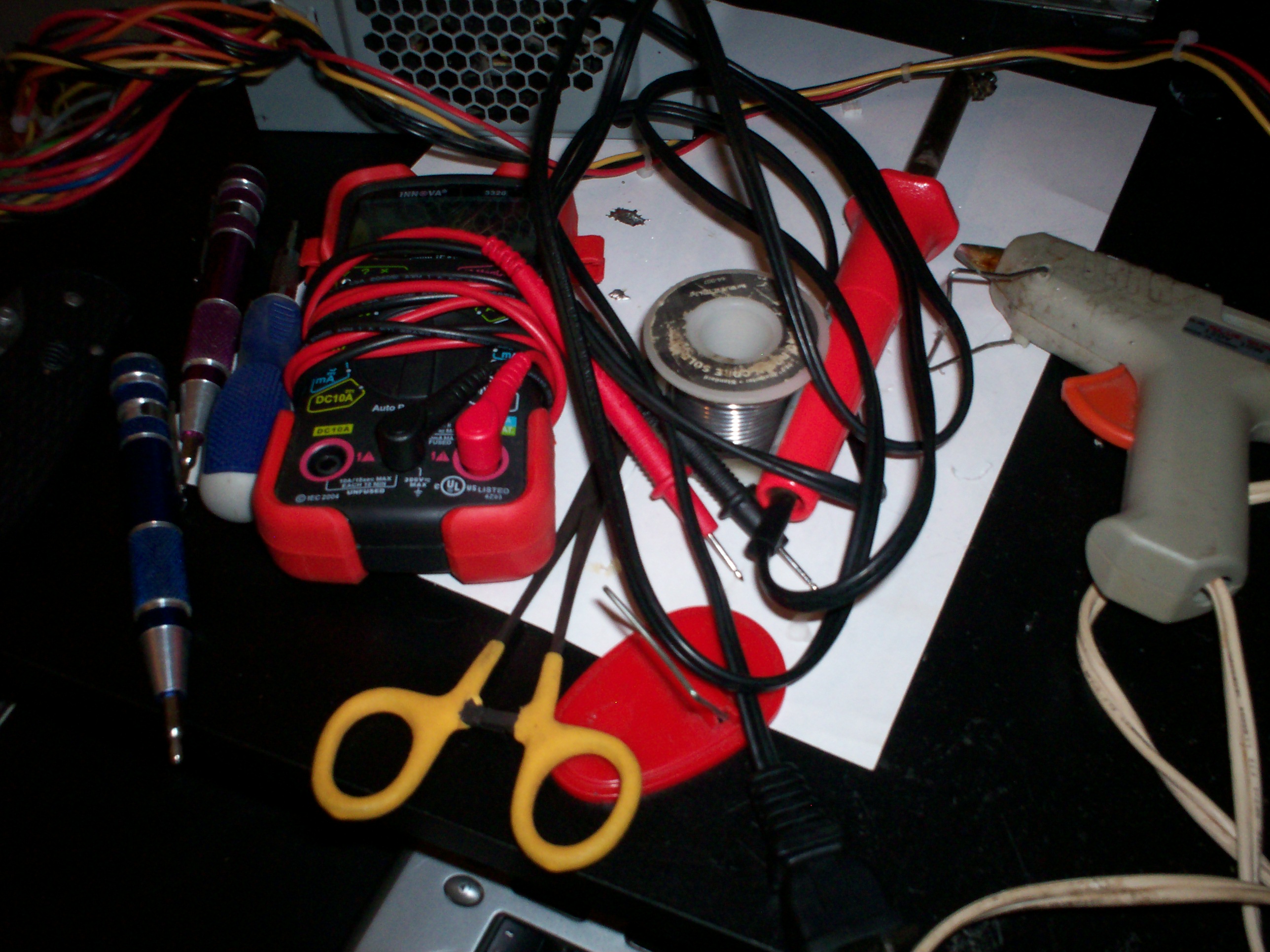
Tools
Soldering iron
Screw drivers
Hot glue gun/epoxy
Pliers
Software for testing. Win 98/XP
Parmon
PSU

Cut the green wire and insert it into any black wire or put a switch inline between the same.
Floppy power connectors
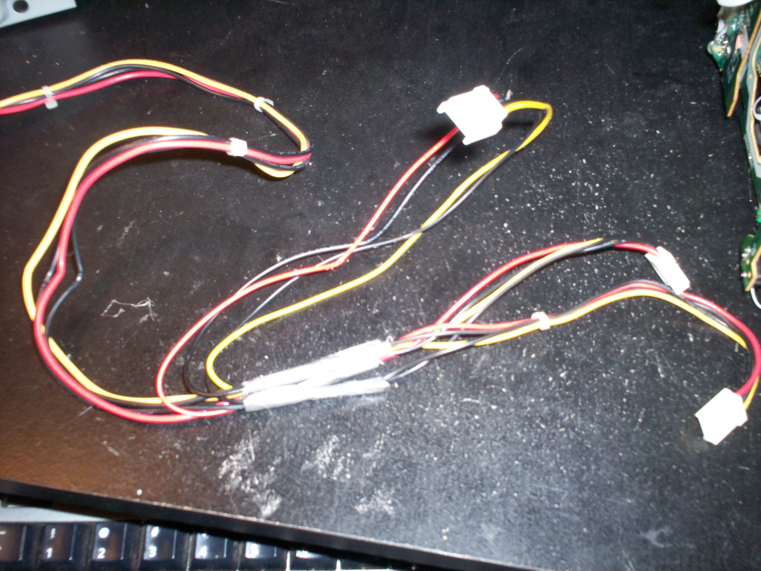
Take your floppy drive power connectors, match the colors and solder them together to form a 3 way pigtail.
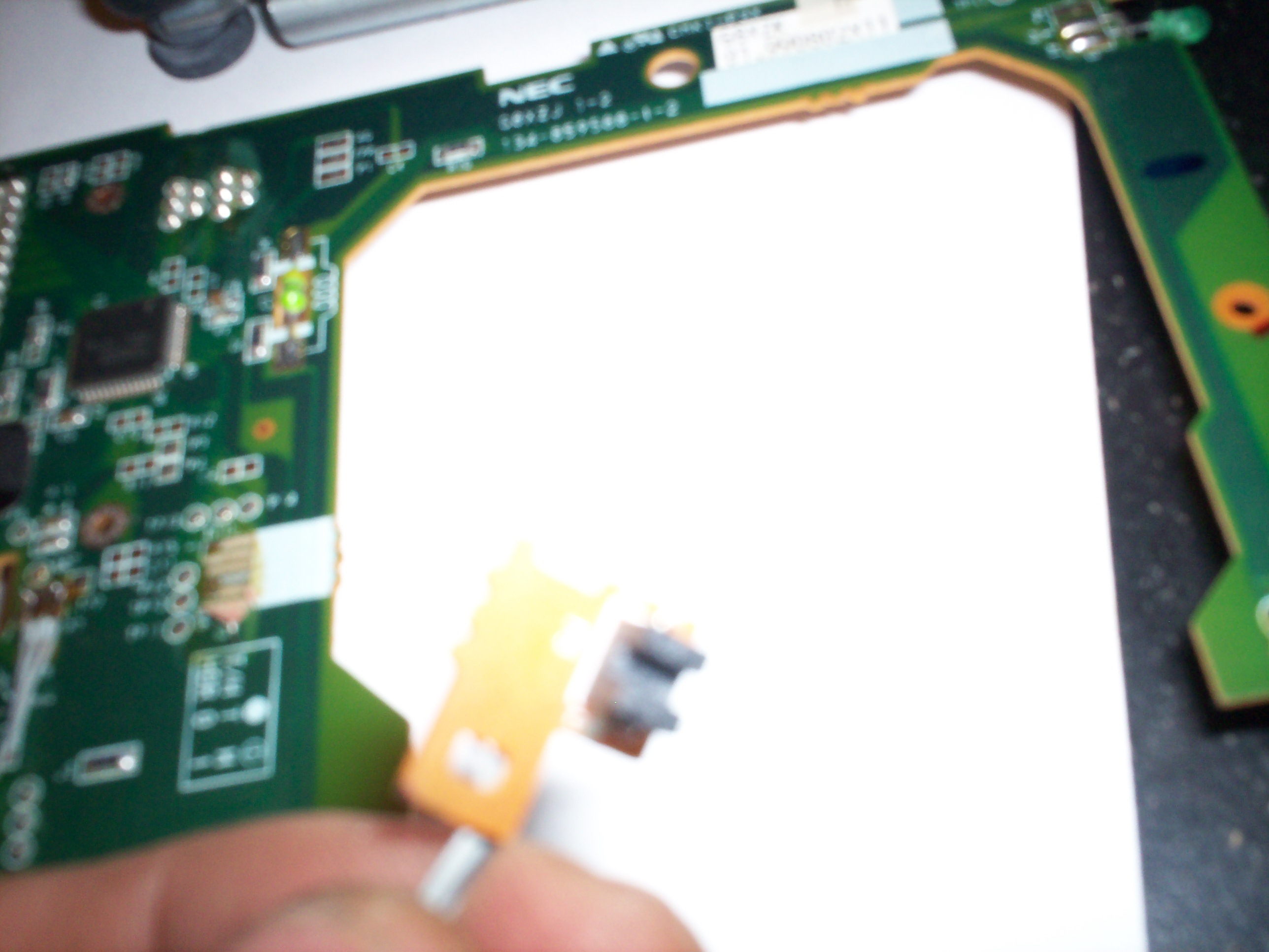
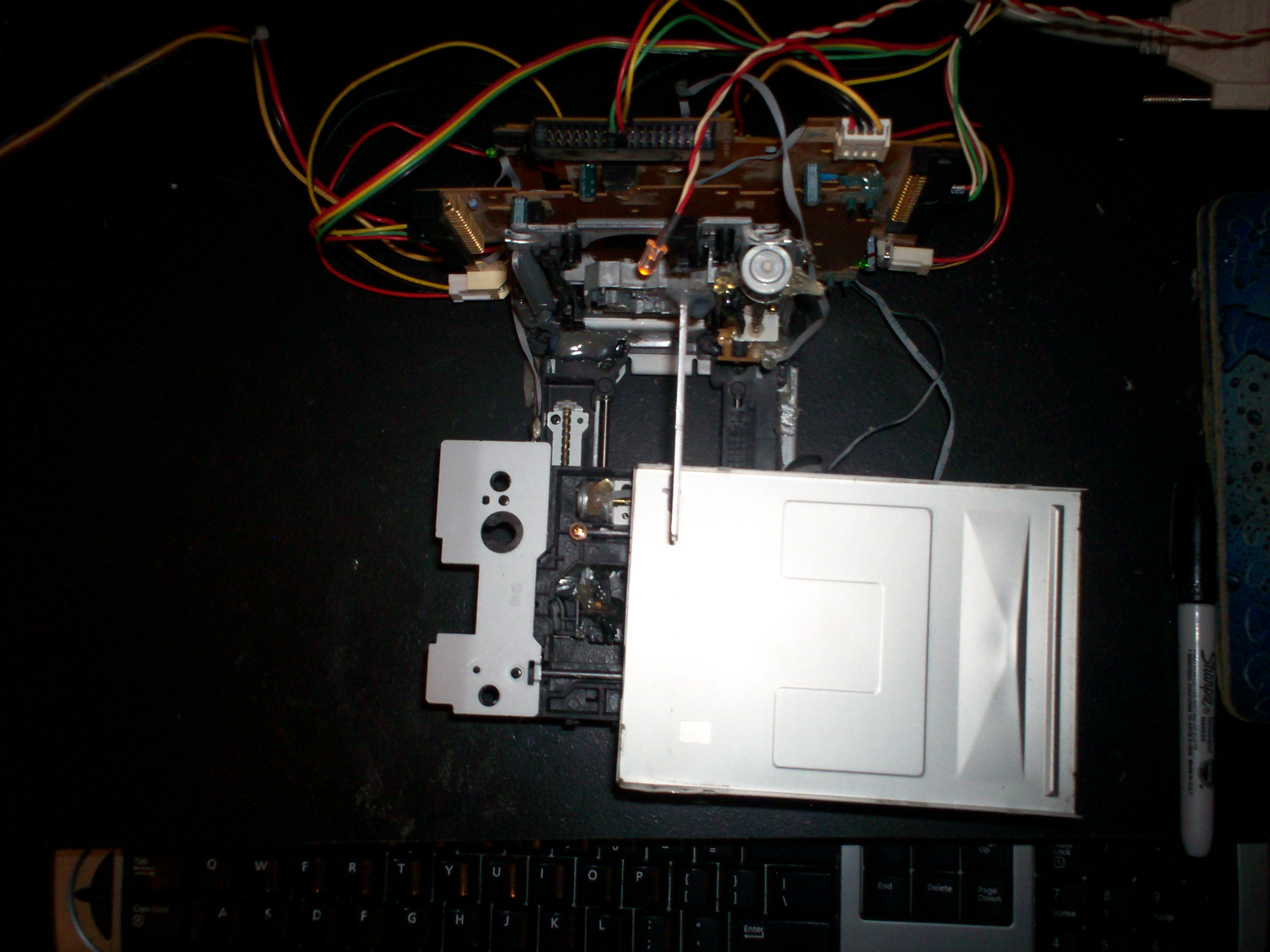
Floppy Controller
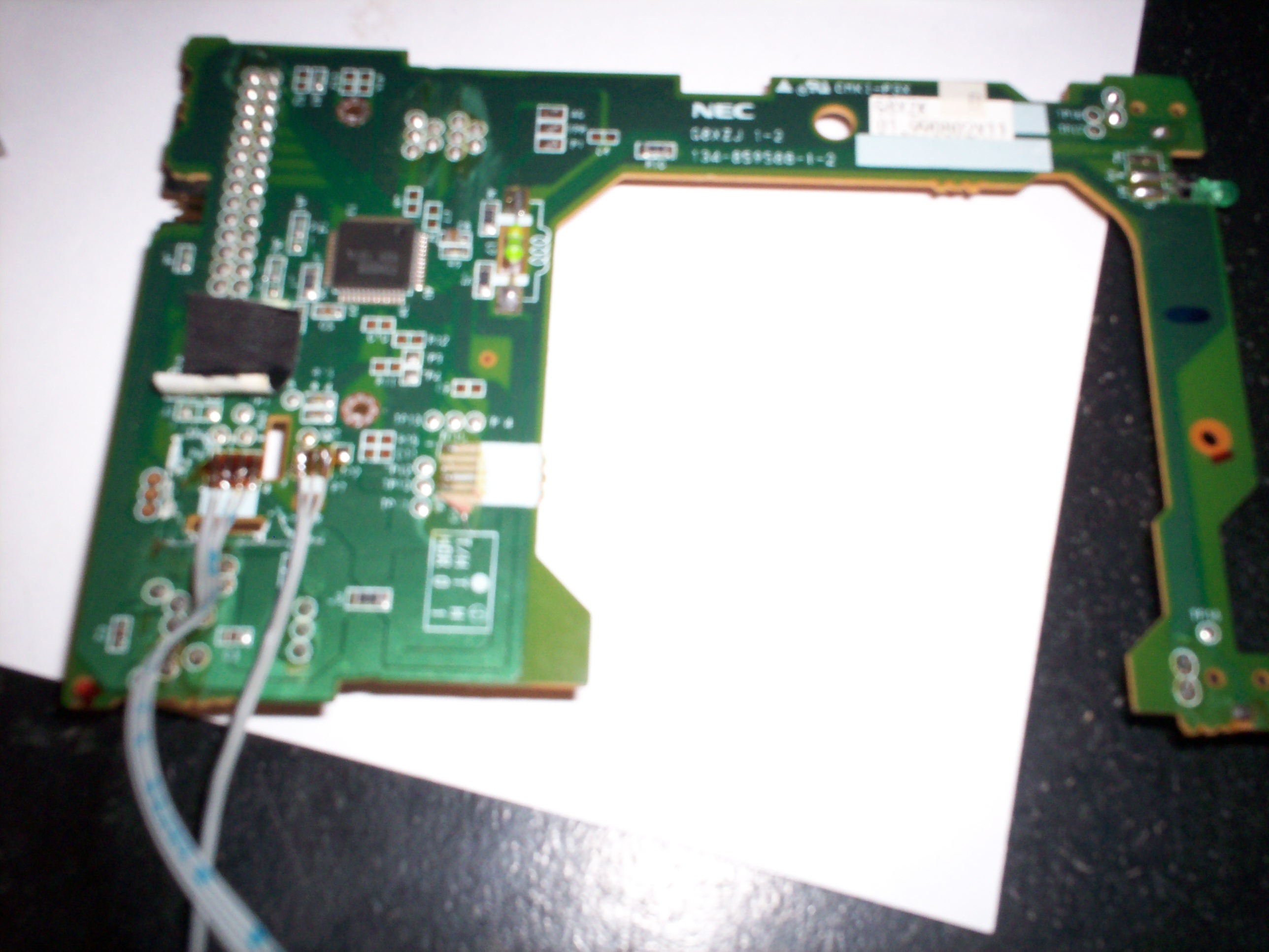
Wires added from the ide ribbon cable to the original locations for the stepper motor and light sensor, on the floppy controller board.
Just match the original wire order to the replacement.
Cd rom sled X3
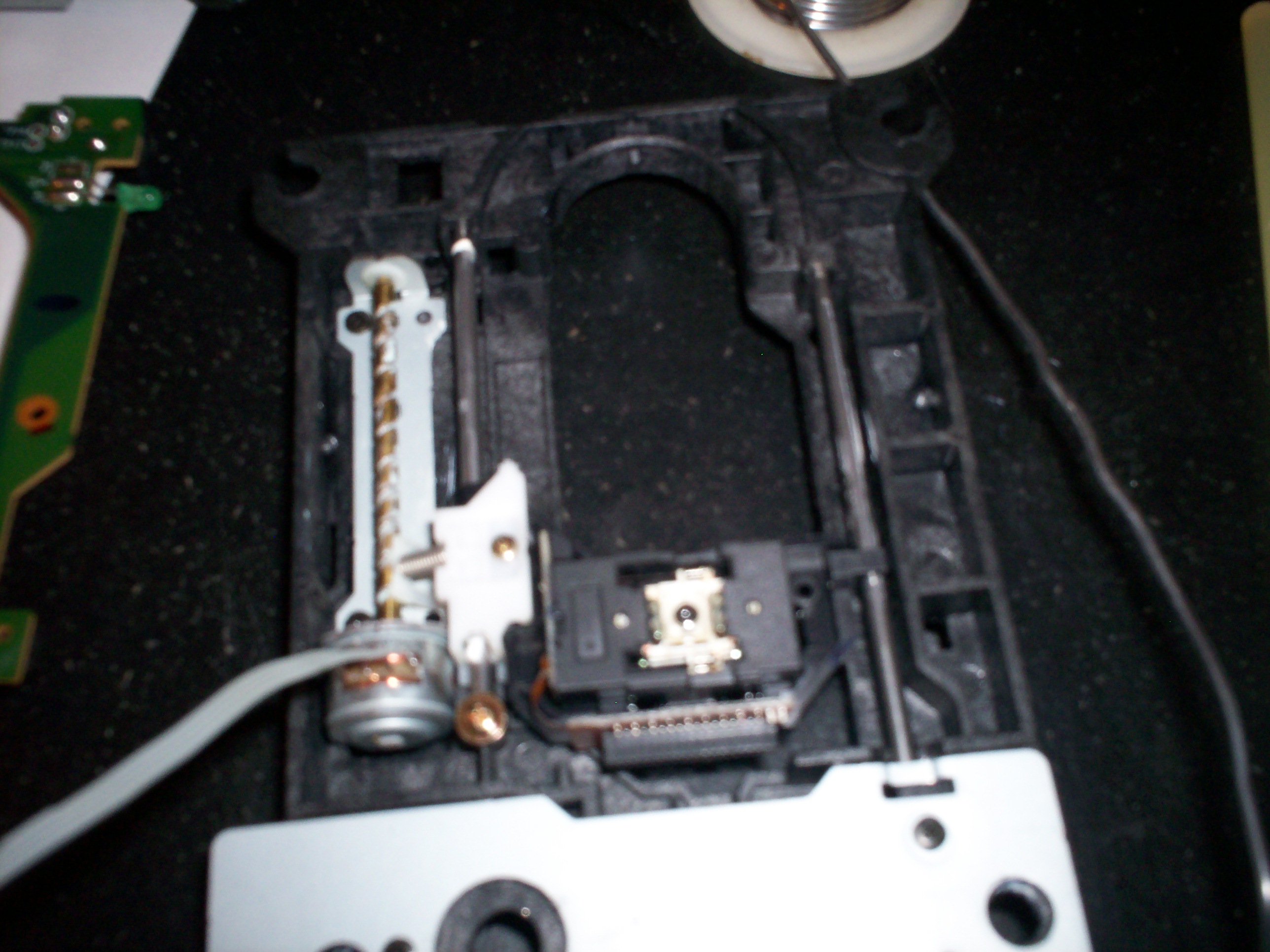
Attach wires from floppy drive controller to stepper motor. 1234-1234 If you get it wrong it wont hurt anything.
Place light sensor on the frame and a plastic tab or zip pie part on the sled to insert into sensor at end of sled travel.
Light sensor
Explained above.
Data connections.
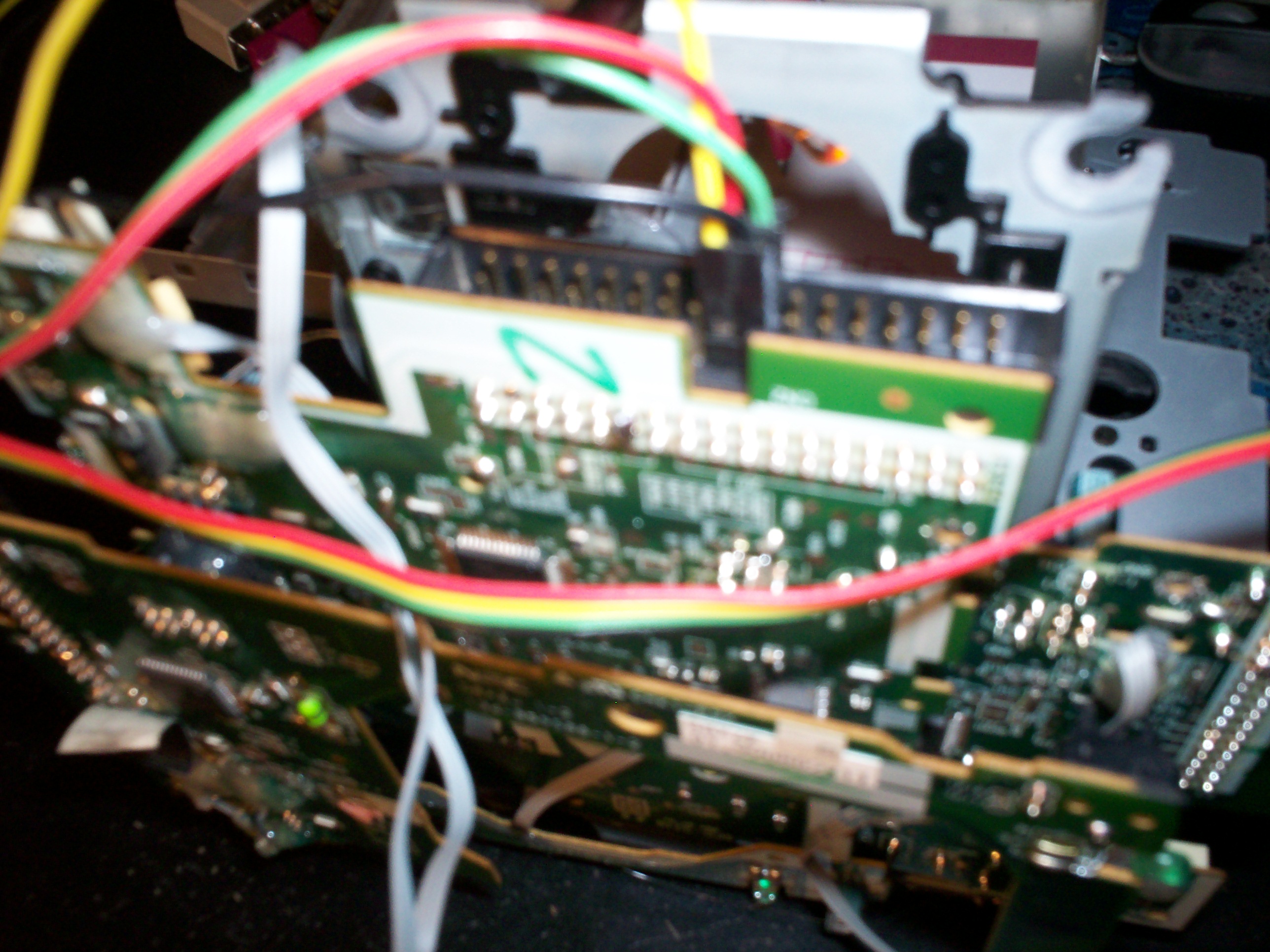
Solder pins 11 and 12 together on the floppy controller or use a jumper from the cd roms

Pins 18 and 20 are direction and step (respectively)
Pins 17 and 19 for the grounds.
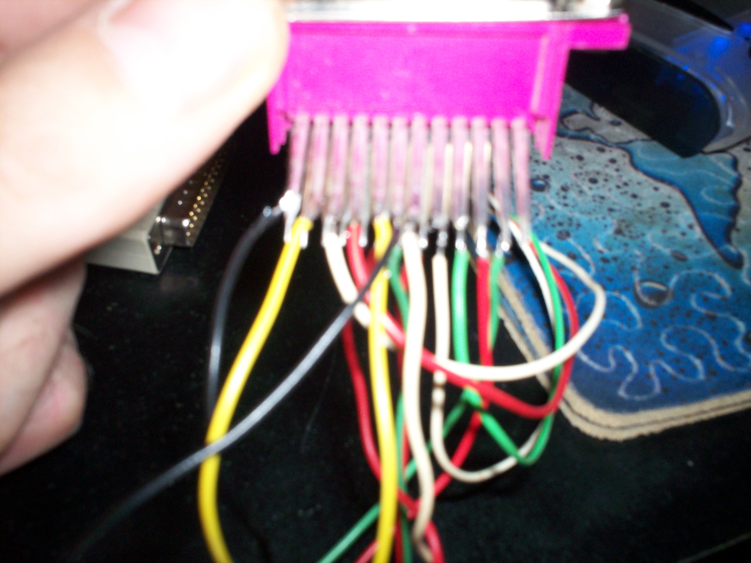
Parallel port pinout
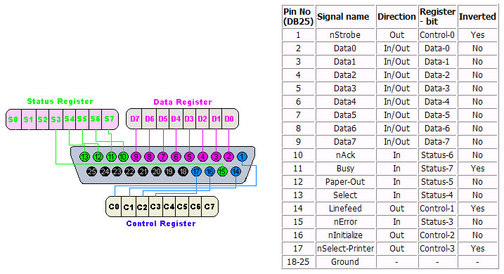
Use pins 2-9 for direction and step respectively for each axis.
Use pins 18-25 for the grounds. The order dont matter on them.
Parallel port
X and Z axis glued together.
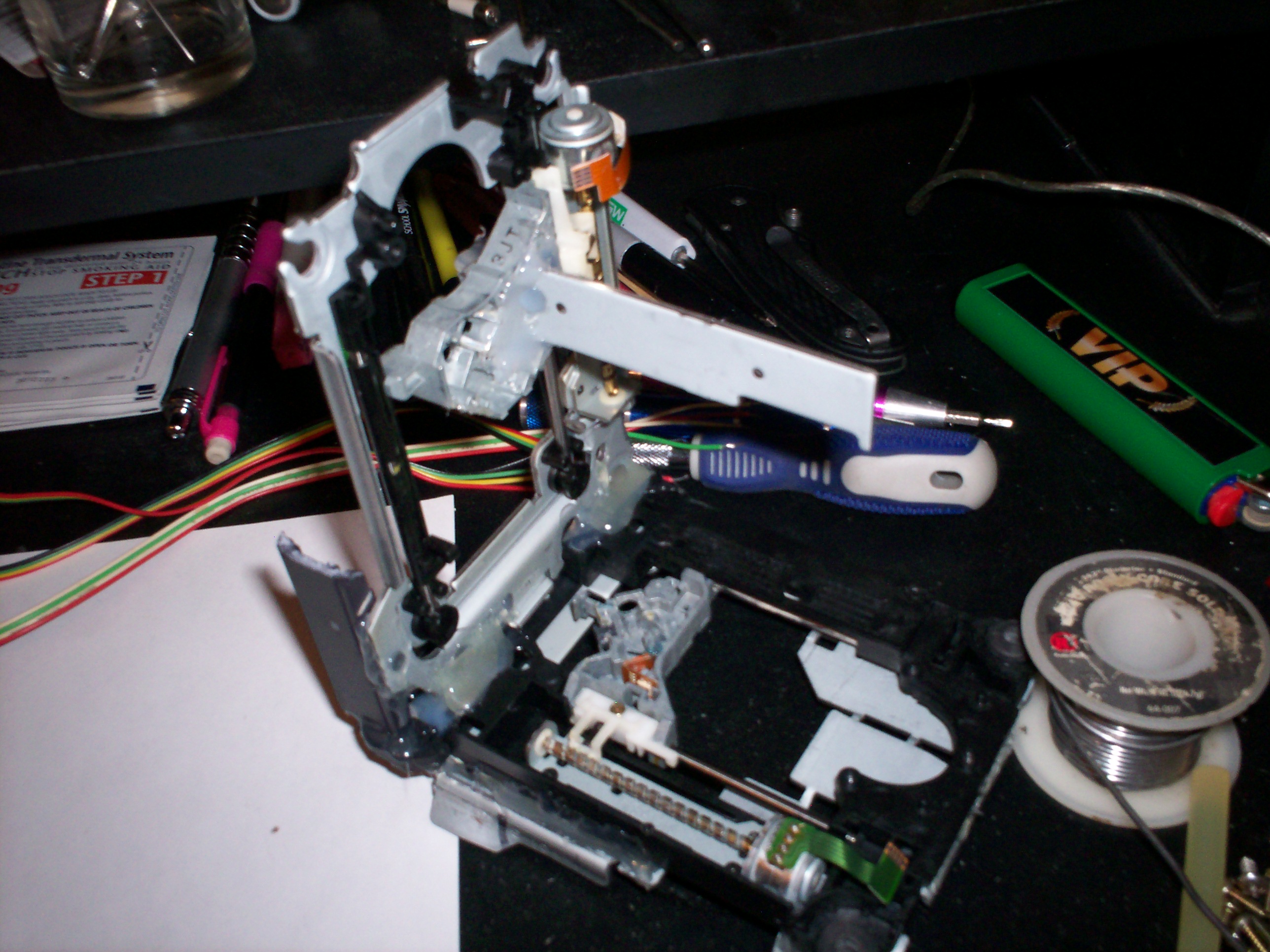
Tool arm attached
Y axis sled attached
Working table installed
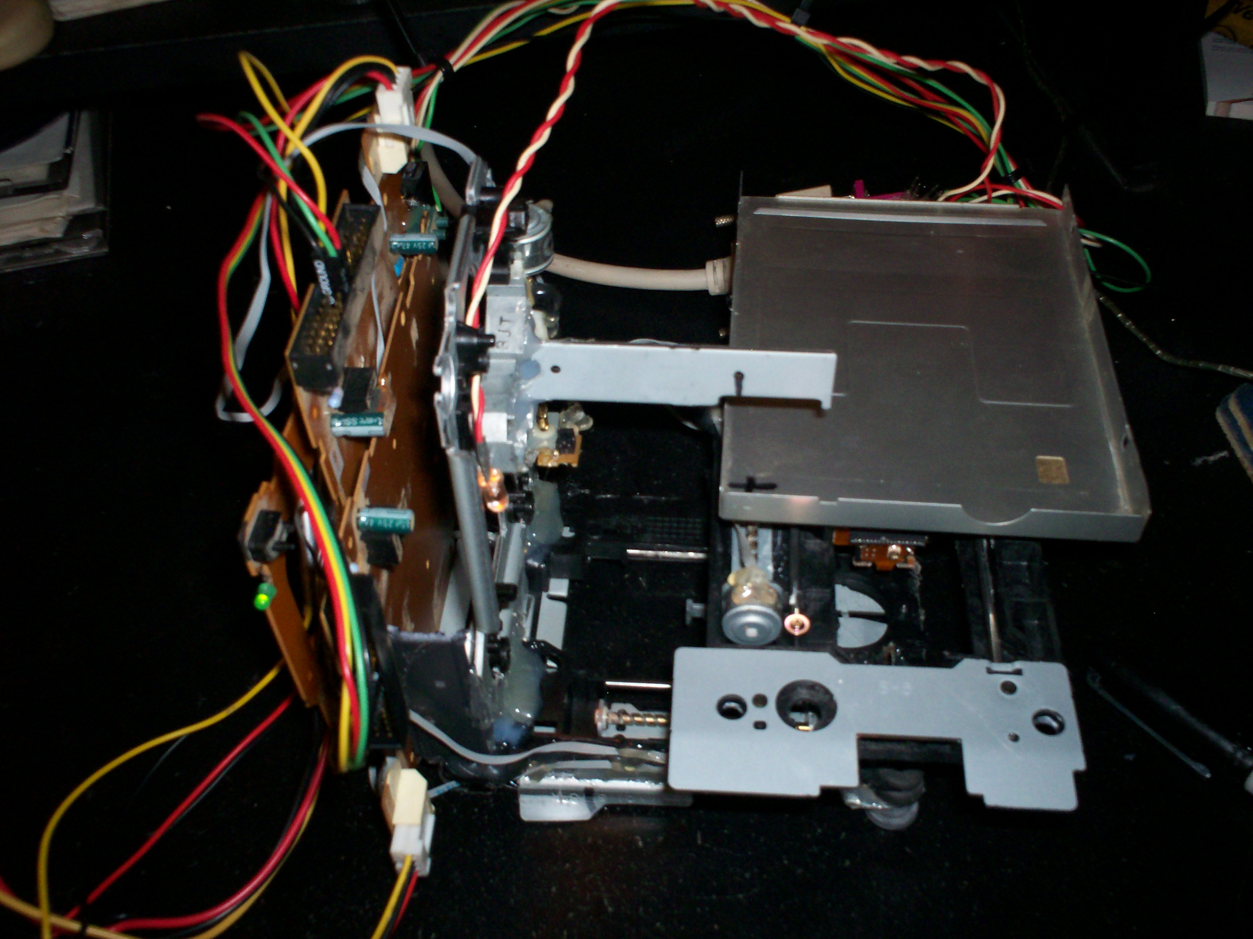
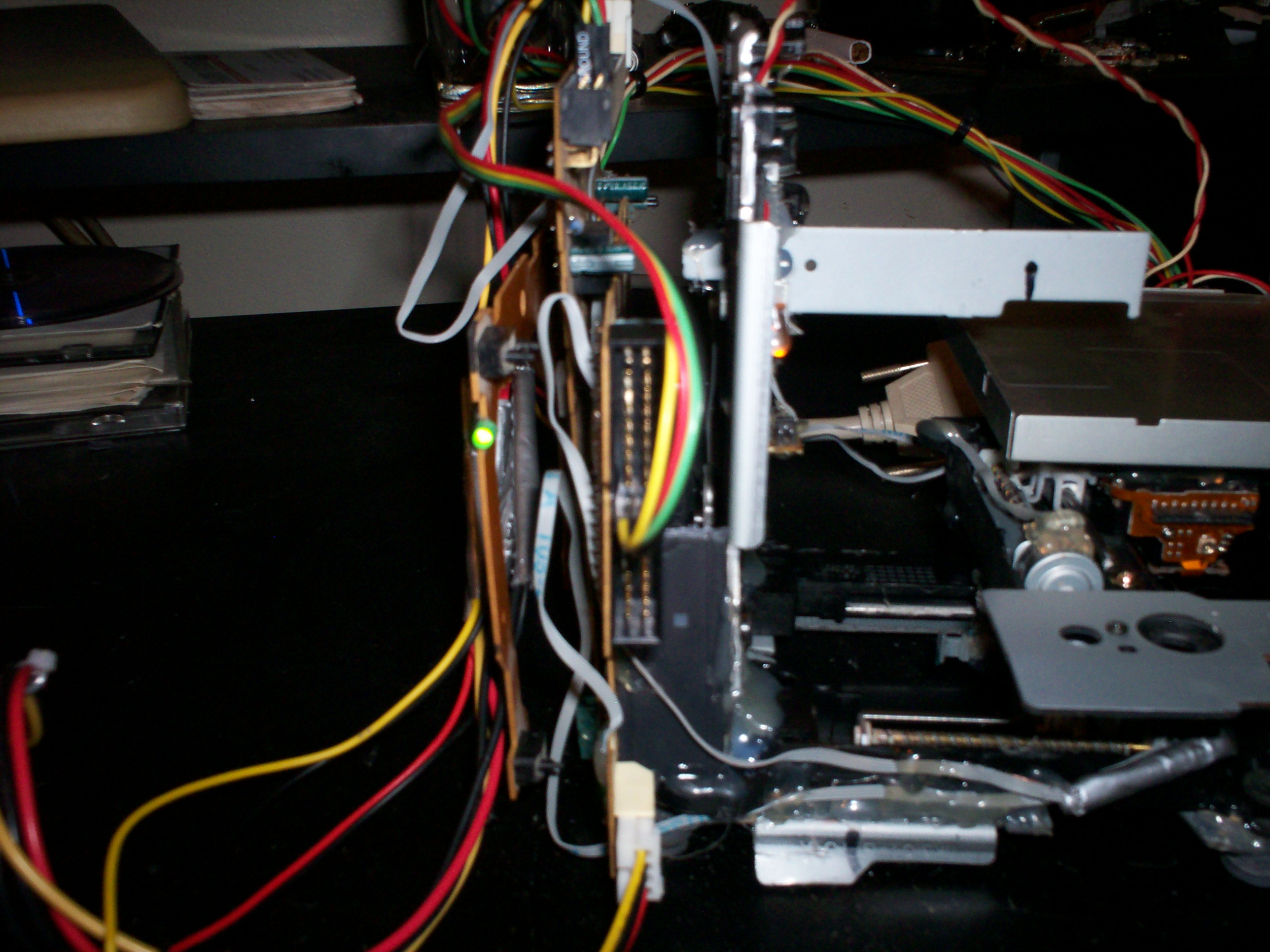
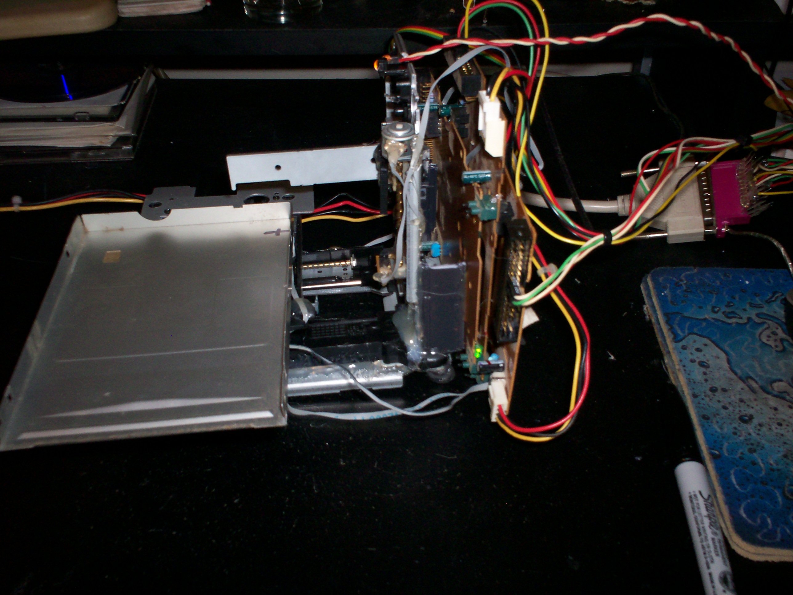
I stacked all my controller boards on the rear and glued them, making sure no components would touch and short out.
Hello

Some manual action using parmon to toggle the axises.
Video
(Video wont embed)
I had a couple technical glitches along the way, i didn't edit them out of the video.
Learning is all part of the process.
Remember that you can make anything your heart desires with a little patience and an open mind.
If you want to tackle this, feel free to get a hold of me with questions.
Stay tuned for V2.0
Hope you enjoyed.
After two days of coffee fueled futzing, i have come up with my first multi use mill.
This is a rough draft i plan to expand on. I'm going to tackle the same project on a bigger scale.
Made out of 100% recycled computer parts, that would undoubtedly would end up in a landfill or third world country.
I have not got down to working with cnc and cad software yet.
This project was inspired by some youtube videos. I found his instructions were not quite correct.
So i have fixed them here in the thread. I used his videos as reference material and worked out the kinks myself.
Your mileage may vary. I still recommend watching them for some good info.
Richard Harris Youtube
Made out of 100% recycled computer parts, that would undoubtedly would end up in a landfill or third world country.
Parts list
3 floppy disk drives bipolar stepper controllers
3 cd/dvd rom/burner the hind with bipolar stepper motors
1 ide ribbon cable to section and use later
1 computer power supply working and some broken ones for floppy power connectors
1 Parallel port from a motherboard
Tools
Soldering iron
Screw drivers
Hot glue gun/epoxy
Pliers
Software for testing. Win 98/XP
Parmon
PSU
Cut the green wire and insert it into any black wire or put a switch inline between the same.
Floppy power connectors
Take your floppy drive power connectors, match the colors and solder them together to form a 3 way pigtail.
Floppy Controller
Wires added from the ide ribbon cable to the original locations for the stepper motor and light sensor, on the floppy controller board.
Just match the original wire order to the replacement.
Cd rom sled X3
Attach wires from floppy drive controller to stepper motor. 1234-1234 If you get it wrong it wont hurt anything.
Place light sensor on the frame and a plastic tab or zip pie part on the sled to insert into sensor at end of sled travel.
Light sensor
Explained above.
Data connections.
Solder pins 11 and 12 together on the floppy controller or use a jumper from the cd roms
Pins 18 and 20 are direction and step (respectively)
Pins 17 and 19 for the grounds.
Parallel port pinout
Use pins 2-9 for direction and step respectively for each axis.
Use pins 18-25 for the grounds. The order dont matter on them.
Parallel port
X and Z axis glued together.
Tool arm attached
Y axis sled attached
Working table installed
I stacked all my controller boards on the rear and glued them, making sure no components would touch and short out.
Hello
Some manual action using parmon to toggle the axises.
Video
(Video wont embed)
I had a couple technical glitches along the way, i didn't edit them out of the video.
Learning is all part of the process.
Remember that you can make anything your heart desires with a little patience and an open mind.
If you want to tackle this, feel free to get a hold of me with questions.
Stay tuned for V2.0
Hope you enjoyed.
edit on 1/24/2014 by shaneslaughta because: (no reason given)
edit on 1/24/2014 by shaneslaughta because: (no reason
given)
S+F
Wow that looks like a lot of work but it's awesome how you can figure that all out from a video. Is it just for writing? Do you have plans on making a bigger one at all? Nice work nonetheless.
Wow that looks like a lot of work but it's awesome how you can figure that all out from a video. Is it just for writing? Do you have plans on making a bigger one at all? Nice work nonetheless.
reply to post by thov420
Its not that hard to be honest. I think anyone could build it if they are dedicated to the pursuit of knowledge.
It can do more than write. It can cut vinyl stickers, it can shape solid material in three dimensions.
Provided you put a knife on it or shaping bits., kind of like a drill bit.
The parallel ports on computers have enough data connections to control up to 4 axis, or three axis and a motor for the drill bits.
Its all a matter of what you want to do with it and how far you let your imagination take you.
The next version will be made from printers or scanners. Bigger range of movement for bigger projects.
Awesome. I guess you could use it for just about anything your mind can think of. I'm kinda interested in CNC and CAD and this seems like a super
cheap way to practice compared to a $10k+ CNC mill.
reply to post by shaneslaughta
That is pretty cool but I would not want to write the programs for it.
How did you write hello? Manually touching the connectors?
That is pretty cool but I would not want to write the programs for it.
How did you write hello? Manually touching the connectors?
reply to post by Bleeeeep
Using the program parmon, it allows you to manually toggle the output of your parallel port controlling the movements.
There is a program for linux that will control this device. Insert your cad drawing and output the gcode to the plotter.
Using the program parmon, it allows you to manually toggle the output of your parallel port controlling the movements.
There is a program for linux that will control this device. Insert your cad drawing and output the gcode to the plotter.
thov420
Awesome. I guess you could use it for just about anything your mind can think of. I'm kinda interested in CNC and CAD and this seems like a super cheap way to practice compared to a $10k+ CNC mill.
Also green method. Why toss out parts that could be re-sourced into a useful project.
I am venturing now into the software aspect. Starting with basic shapes and patterns.
If all goes well from here, i will make and install a basic cutter head and try my hand, or rather the bots hand and milling.
I will post my results in a while.
If all goes well from here, i will make and install a basic cutter head and try my hand, or rather the bots hand and milling.
I will post my results in a while.
I found a great piece of software called Mach3. Fully customizable in every respect.
It has a hell of a learning curve. This might take me a while to figure out.
If there are any machinist on the board i would be grateful for your input here.
It has a hell of a learning curve. This might take me a while to figure out.
If there are any machinist on the board i would be grateful for your input here.
new topics
-
President BIDEN Vows to Make Americans Pay More Federal Taxes in 2025 - Political Suicide.
2024 Elections: 1 hours ago -
Ode to Artemis
General Chit Chat: 2 hours ago -
Ditching physical money
History: 5 hours ago -
One Flame Throwing Robot Dog for Christmas Please!
Weaponry: 5 hours ago -
Don't take advantage of people just because it seems easy it will backfire
Rant: 6 hours ago -
VirginOfGrand says hello
Introductions: 7 hours ago -
Should Biden Replace Harris With AOC On the 2024 Democrat Ticket?
2024 Elections: 7 hours ago -
University student disciplined after saying veganism is wrong and gender fluidity is stupid
Education and Media: 10 hours ago -
Geddy Lee in Conversation with Alex Lifeson - My Effin’ Life
People: 11 hours ago -
God lived as a Devil Dog.
Short Stories: 11 hours ago
top topics
-
Hate makes for strange bedfellows
US Political Madness: 15 hours ago, 20 flags -
University student disciplined after saying veganism is wrong and gender fluidity is stupid
Education and Media: 10 hours ago, 12 flags -
Police clash with St George’s Day protesters at central London rally
Social Issues and Civil Unrest: 13 hours ago, 9 flags -
President BIDEN Vows to Make Americans Pay More Federal Taxes in 2025 - Political Suicide.
2024 Elections: 1 hours ago, 7 flags -
TLDR post about ATS and why I love it and hope we all stay together somewhere
General Chit Chat: 13 hours ago, 7 flags -
Should Biden Replace Harris With AOC On the 2024 Democrat Ticket?
2024 Elections: 7 hours ago, 6 flags -
Don't take advantage of people just because it seems easy it will backfire
Rant: 6 hours ago, 4 flags -
One Flame Throwing Robot Dog for Christmas Please!
Weaponry: 5 hours ago, 4 flags -
God lived as a Devil Dog.
Short Stories: 11 hours ago, 3 flags -
Ditching physical money
History: 5 hours ago, 3 flags
active topics
-
The Superstition of Full Moons Filling Hospitals Turns Out To Be True!
Medical Issues & Conspiracies • 22 • : mooncake -
University student disciplined after saying veganism is wrong and gender fluidity is stupid
Education and Media • 23 • : BigDuckEnergy -
President BIDEN Vows to Make Americans Pay More Federal Taxes in 2025 - Political Suicide.
2024 Elections • 3 • : BingoMcGoof -
Russia Ukraine Update Thread - part 3
World War Three • 5717 • : Arbitrageur -
Should Biden Replace Harris With AOC On the 2024 Democrat Ticket?
2024 Elections • 44 • : budzprime69 -
Hundreds of teenagers flood into downtown Chicago, smashing car windows
Other Current Events • 111 • : 777Vader -
British TV Presenter Refuses To Use Guest's Preferred Pronouns
Education and Media • 125 • : Annee -
Who guards the guards
US Political Madness • 4 • : kwaka -
New whistleblower Jason Sands speaks on Twitter Spaces last night.
Aliens and UFOs • 44 • : pianopraze -
"We're All Hamas" Heard at Columbia University Protests
Social Issues and Civil Unrest • 263 • : YourFaceAgain
8