It looks like you're using an Ad Blocker.
Please white-list or disable AboveTopSecret.com in your ad-blocking tool.
Thank you.
Some features of ATS will be disabled while you continue to use an ad-blocker.

Free energy machine powered by gravity. BRAZIL
page: 10share:
reply to post by Heliophant
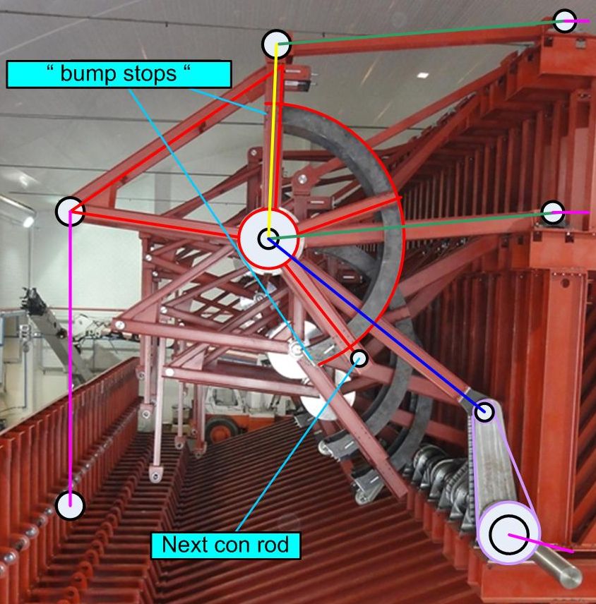
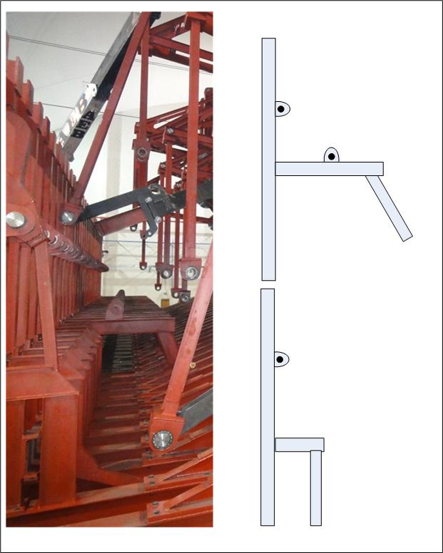
the unpainted " black bars " are IMHO stiffeners - they are clearly bolted to the subframe - and further they support a " bump stop " - to limit range of motion [ rotation ] of the subassy. , further - they have studs intended to mount a further peice of the increasingly baroque contraption
please study :
this is a better proportioned diagram - based on the latest released pic
as i state previously - the entire sub-assy. lined in red is one rigid structure - that pivots around the king pin at the joint of con rod yellow / green / blue
further - it has " bumpstops " to limit its motion
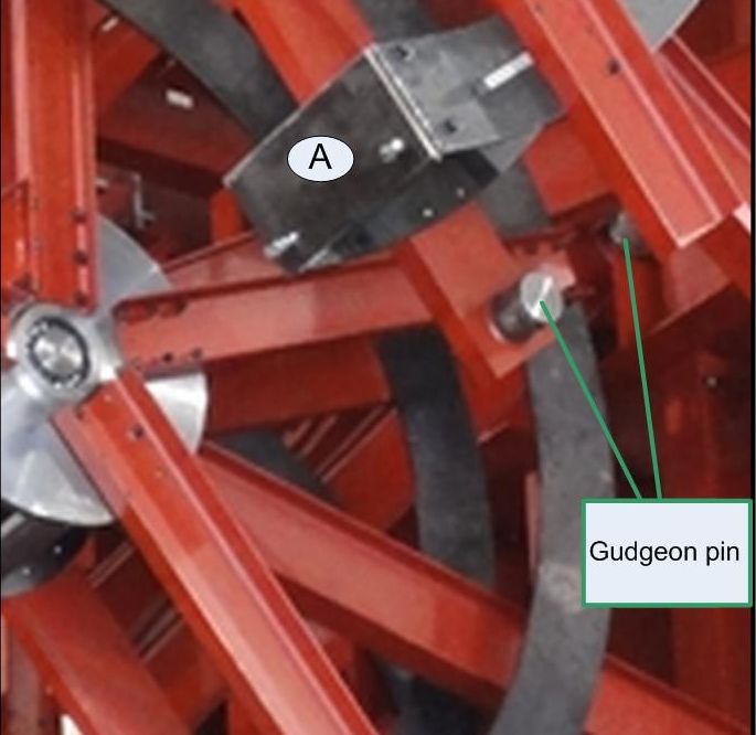
lastly - it has 2 gudgeon pins - wich will provide a pivot for a further conrod
and finally - there is provision on the un painted supports for a further part to be bolted to it [ 2 studs ]
see :
where this is taking the " project " - i cannot speculate - but its heading into bizarre land
the unpainted " black bars " are IMHO stiffeners - they are clearly bolted to the subframe - and further they support a " bump stop " - to limit range of motion [ rotation ] of the subassy. , further - they have studs intended to mount a further peice of the increasingly baroque contraption
please study :
this is a better proportioned diagram - based on the latest released pic
as i state previously - the entire sub-assy. lined in red is one rigid structure - that pivots around the king pin at the joint of con rod yellow / green / blue
further - it has " bumpstops " to limit its motion
lastly - it has 2 gudgeon pins - wich will provide a pivot for a further conrod
and finally - there is provision on the un painted supports for a further part to be bolted to it [ 2 studs ]
see :
where this is taking the " project " - i cannot speculate - but its heading into bizarre land
why " gravity motors " do not work - for dummies
all previous " gravity motor designs " - boil down to this concept :
the delusion that if the distance between the operating mass and the centre of rotation can be dynamically adjusted , then the lever principal will cause oposed masses to produce a greater forces as they " fall " than is required to " lift " them
while the principlal starts off on solid ground see :
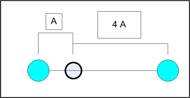
while it is true that the mass on the right will exert 4 times the torque as the mass on the left as the unit rotates through 90 degrees
it utterly collapses - in practice - because the energy required to alter the distance [ of the operating weights ] from the centre of rotation + losses from friction are higher than the energies " gained " by the falling masses exerting a greater torque than the masses being ` lifted `
this is why any closed system reliant on " weights " cannot maintain " perpetual motion "
all previous " gravity motor designs " - boil down to this concept :
the delusion that if the distance between the operating mass and the centre of rotation can be dynamically adjusted , then the lever principal will cause oposed masses to produce a greater forces as they " fall " than is required to " lift " them
while the principlal starts off on solid ground see :
while it is true that the mass on the right will exert 4 times the torque as the mass on the left as the unit rotates through 90 degrees
it utterly collapses - in practice - because the energy required to alter the distance [ of the operating weights ] from the centre of rotation + losses from friction are higher than the energies " gained " by the falling masses exerting a greater torque than the masses being ` lifted `
this is why any closed system reliant on " weights " cannot maintain " perpetual motion "
The more complex and impressive you make something, the more money you can sell its promises for. You can't get something for nothing.
reply to post by ignorant_ape
Thanks, that does help a bit. The whole construction is still a bit mystifying, but I'm fascinated. Free Energy or Gas Powered, I just want to see this monstrosity in motion!
Thanks, that does help a bit. The whole construction is still a bit mystifying, but I'm fascinated. Free Energy or Gas Powered, I just want to see this monstrosity in motion!
reply to post by Wifibrains
indeed they have - and my stance on this tail has solidified - i entered this thread , more with a sense of engineering curiousity - but now can fairly confidently declare that its a farce
its time to play " spot the difference "
sadly - i canot give this post the attention it deserves just now - but will tonight [ in about 12 hours ]
but just to say - compare pic # 33 / 34 / 35 / 36 / 37
then go back to : pic # 2 / 3 / 11 / 13 / 16 / 21 / 22 / 23 / 24
i dismissed minor ` irks ` due to issues of perspective / camera angle etc - but now the elephant is in the room - and its unmistakable - the pics are a joke
i always had grave doubts about the science - but now the reality of the entire thing is in doubt
reply to post by ignorant_ape
I tried, but it's hard to play spot the difference when pics are not side by side. Give us a clue.
I tried, but it's hard to play spot the difference when pics are not side by side. Give us a clue.
hey - sorry for the delay - just not had time [ still dont - so this will be quick and dirty ]
the pictures purport to be a chronical of the building of an aledged " gravity engine " and while the exif data shows that the pics are in date order , the " build " has most certainly not been linear :
i had a few irks with the pics - but to save time - i will jump straight to the killer - the mutation of the " device "
a key structure that i will refer to as subframe C , has morphed - its origional confiveration :
subframe C : v1.0
has now been replace by
subframe C : v2.0
there could be a valid reason - but as the " project " is now 3 months " in construction " with the only " documentation " being random pictures with no explaination
i am inclined to assume the worst
here is the evidence of the swap [ using a crop from pic # 37 ] :
with an outline of subframe C v1.0 top and v2.0 bottom
i also note that the newer version is welded to the bottom subframe - all previous assembly joints have been bolted
this is a major " design change "
and there are no rational reasons that spring to mind to explain it [ in the context of a legitimate build of this alledged " gravity engine " ]
other explainations - include - :
1 - the "design " is fataly flawed and requires redesign
2 - this is nothing to do with " gravity engines " - we are looking at random pics of something " all together different "
thats all for now - sorry
reply to post by ignorant_ape
I did actually notice that. Even though it looks like a mistake has been made and the designs have been thrown out the window, there could be method to the madness.
If the peice they have cut out was part of the structure and those holes were to be used for a pin to create a pivot point, they may very well be in trouble. I can't see why they have had to get that part out the way, as the arm seems to move Inbetween the supports. Whatever the reason, it looks like a hell of a job to put right.
I remain interested and optimistic, but confused none the less.
New photos added today. Not of the machine but of the beginning stages of the machine to be built in gilman Illinois USA. Nothing to see really, large
concrete patch. Lol
www.rarenergia.com.br...
www.rarenergia.com.br...
edit on 11-6-2013 by Wifibrains because: (no reason given)
Originally posted by Wifibrains
reply to post by Bedlam
it takes less energy to keep something swinging than it does to start it swinging because of gravity works with you half the time as opposed to against you all the time.
Of course it takes less energy to "keep something swinging" because you already had to spent more energy in the beginning to get the system going - it's entirely irrelevant. What counts is how much energy IN and how much out.
If I were thinking like you, I'd claim to have made a sensational "free energy" machine which only uses very little energy to produce MUCH more, it's a 100 ton rock which I push down a mountain. (And then some system which can harness the energy of the mass coming down the mountain)
Of course, I conveniently don't mention the fact that the 100 ton rock FIRST needs to get up there first...
You do the same thing by disregarding the energy which is required to get the swing going.
If it were so easy, why not build a simple pendulum "thing" which starts a pendulum swinging which is connected to a dynamo....and then in regular intervals pushes the pendulum with somewhat less energy and "harvesting" the free energy created from the swings with the dynamo? (Eg...grandfather's clock...good example). Problem: The energy to put in will ALWAYS be greater than the energy out. (The longer, heaver the pendulum, the longer it might swing, but the more energy is needed to start it ..the more energy is also lost in the upward swing etc. because gravity works against it too.
Ermagherd this is taking way too long to build. Hopefully this last pass of new plates and connections down the "front" row is the last thing they
have to do. Oh and attach the rest of those black slider things.
But knowing our luck, they probably won't try to "power" it up until they've attached the shaft to a generator or something. We'll be watching them install that for another 3 months. Then we'll have to wait for the new power-grid to be built and connected to its output...
C'mon somebody, film this thing in motion! We already know how photogenic this thing is... And someone obviously has a camera fetish. Can we at least get a video of somebody talking about how its supposed to work?
I need answers. And more patience. Fresh out.
edit on 14-6-2013 by Heliophant because: (no reason given)
not a very helpfull " update " - BUT on thursday , 13th JUNE 2013 - i sent emails to RAR energia [ brazil ] and incobrasa soyabean [ illinois ] with
quite plain requests for very basic information
as apart from icreasingly incomprehensible pictures - there is no actuall info from either company being released
- its a secret jim - but not as we know it
due to time zone differences - both mails would have arrived in the company inboxes before ` normal office hours ` - so they have now had 7 working days to reply
and the silence is deafening
one has to , of course draw ones own conclusions from this refusal to even acknowledge inquiries - let alone respond to questions
i will leave it at that - with the note that the 40 pics now make the design " public domain " - and it is as yet unpatented
More energy has been used in taking and posting the pictures and ATS members looking at them than this heap of scrap will generate another free energy
EPIC FAILURE.
When will they learn
When will they learn
reply to post by wmd_2008
Epic failure? How so, it's not finished being built yet!
I can see how the mechanism works by pulling the weights in close to the crank as it turns clockwise and lifts up. On the down drop the weights slide out away from the crank. Along the length of the shaft, the shape of the sign wave indicates the way the gravity energy is transferred.
Friction is this machines biggest issue due to all the moving parts, there are hundreds. If the weights work correctly and over come the friction, it will work.
Originally posted by Wifibrains
reply to post by wmd_2008
Epic failure? How so, it's not finished being built yet!
I can see how the mechanism works by pulling the weights in close to the crank as it turns clockwise and lifts up. On the down drop the weights slide out away from the crank. Along the length of the shaft, the shape of the sign wave indicates the way the gravity energy is transferred.
Friction is this machines biggest issue due to all the moving parts, there are hundreds. If the weights work correctly and over come the friction, it will work.
I noticed the sine wave too, thought it might be significant to the operation of the engine actually but cannot find any more to go on in that direction.
Was thinking along the lines of an AC sine wave, with the frequency peaks scaled up or down (closer or further apart) depending on the size of the engine, but always in keeping with a domestic AC supply.
Could be way off, i'm really only musing about it atm, but it's intriquing nonetheless.
ETA..they must know this approach works, as they claim to have built and tested a smaller engine as a proof of concept device. They wouldn't then go on to build this gargantuan machine on a 'let's build it, it might work' whim.
There is real money being spent on this engine...i dread to think how much money and effort has gone into it.
Would any one of us build such an expensive and expansive device if we were not sure it would work as described...not only that, would you build it, take out 5 expensive newspaper adverts and put the reputation of your large and successful company on the line too?
This is probably one of the most interesting 'alt energy' devices out there in recent years anyway.
It's a nuts and bolts, physical device that doesn't rely on abstract concepts of ether energy, orgone energy, tapping a vacuum or anything esoteric as is usual with these types of things. It's a real, nuts and bolts machine.
A very large and very expensive...and very public machine.
I can't wait for more news from this build.
edit on 22-6-2013 by MysterX because: added text.
Originally posted by Wifibrains
Friction is this machines biggest issue due to all the moving parts, there are hundreds
Even if there was zero friction it would not work....
If the weights work correctly and over come the friction, it will work.
Why do you claim that?
reply to post by hellobruce
It's not really a claim, as It started with "if". Admittedly a big IF.
I try my best not to make assumptions about things I cannot possibly know by adding words like "if" and "could" presenting things as possibilities.
The claim that it will work, rests on the IF the weights over coming the friction.
If the weights work correctly and over come the friction, it will work.
Why do you claim that?
It's not really a claim, as It started with "if". Admittedly a big IF.
I try my best not to make assumptions about things I cannot possibly know by adding words like "if" and "could" presenting things as possibilities.
The claim that it will work, rests on the IF the weights over coming the friction.
Originally posted by Wifibrains
I try my best not to make assumptions about things I cannot possibly know by adding words like "if" and "could" presenting things as possibilities.
The claim that it will work, rests on the IF the weights over coming the friction.
As I said, even if there was zero friction it still would not work....
new topics
-
God's Righteousness is Greater than Our Wrath
Religion, Faith, And Theology: 3 hours ago -
Electrical tricks for saving money
Education and Media: 6 hours ago -
VP's Secret Service agent brawls with other agents at Andrews
Mainstream News: 7 hours ago -
Sunak spinning the sickness figures
Other Current Events: 8 hours ago -
Nearly 70% Of Americans Want Talks To End War In Ukraine
Political Issues: 8 hours ago -
Late Night with the Devil - a really good unusual modern horror film.
Movies: 10 hours ago -
Cats Used as Live Bait to Train Ferocious Pitbulls in Illegal NYC Dogfighting
Social Issues and Civil Unrest: 11 hours ago
top topics
-
VP's Secret Service agent brawls with other agents at Andrews
Mainstream News: 7 hours ago, 9 flags -
Cats Used as Live Bait to Train Ferocious Pitbulls in Illegal NYC Dogfighting
Social Issues and Civil Unrest: 11 hours ago, 8 flags -
Electrical tricks for saving money
Education and Media: 6 hours ago, 4 flags -
HORRIBLE !! Russian Soldier Drinking Own Urine To Survive In Battle
World War Three: 15 hours ago, 3 flags -
Nearly 70% Of Americans Want Talks To End War In Ukraine
Political Issues: 8 hours ago, 3 flags -
Sunak spinning the sickness figures
Other Current Events: 8 hours ago, 3 flags -
Late Night with the Devil - a really good unusual modern horror film.
Movies: 10 hours ago, 2 flags -
The Good News According to Jesus - Episode 1
Religion, Faith, And Theology: 13 hours ago, 1 flags -
God's Righteousness is Greater than Our Wrath
Religion, Faith, And Theology: 3 hours ago, 0 flags
active topics
-
Mood Music Part VI
Music • 3101 • : ThatSmellsStrange -
VP's Secret Service agent brawls with other agents at Andrews
Mainstream News • 41 • : ThatSmellsStrange -
HORRIBLE !! Russian Soldier Drinking Own Urine To Survive In Battle
World War Three • 32 • : DaRAGE -
New whistleblower Jason Sands speaks on Twitter Spaces last night.
Aliens and UFOs • 55 • : baablacksheep1 -
Cats Used as Live Bait to Train Ferocious Pitbulls in Illegal NYC Dogfighting
Social Issues and Civil Unrest • 20 • : Asher47 -
Nearly 70% Of Americans Want Talks To End War In Ukraine
Political Issues • 12 • : Asher47 -
Electrical tricks for saving money
Education and Media • 4 • : Lumenari -
DONALD J. TRUMP - 2024 Candidate for President - His Communications to Americans and the World.
2024 Elections • 514 • : WeMustCare -
The Acronym Game .. Pt.3
General Chit Chat • 7744 • : bally001 -
Truth Social goes public, be careful not to lose your money
Mainstream News • 128 • : Astyanax