It looks like you're using an Ad Blocker.
Please white-list or disable AboveTopSecret.com in your ad-blocking tool.
Thank you.
Some features of ATS will be disabled while you continue to use an ad-blocker.

NoC versus SoC issue. Let's set the facts straight, once and for all.
page: 2share:
I showed a photo of what Sean Boger would have seen and described, that's about this same 24.9° bank angle.
All the ANC workers also showed this 24.9° bank angle with a toy plane in their hands, showing us how AA 77 approached them, coming towards them, first appearing in their sight, low flying from over the Annex roofs, about 50 feet high over the roofs, see the CIT video shot at the ANC Maintenance buildings yard.
They all said it flew NoC, after it passed over the center of the Annex roofs, in a slight right bank turn towards them, to turn away from them in front of their yard grounds, passing over their parking space just 50 meters/yards outside their maintenance-yard and along Columbia Pike, on its way towards Route 27 and the area just to the right of the Heli pad.
There's a completely normal G-Load of 1.1 Gs in that 24.9° right banked turn attitude, and an increased stall speed of 166 KTS (191 MPH). That's pretty near the rated stall speed of 160 KTS, but still perfectly possible at the 200 KTS initial speed at entering the turn.
There's a 34 KTS speed reserve before any danger of stalling.
We must also take in account that the plane was in a descending attitude, a 8.18° small angle of attack. Thus a slight acceleration must have naturally occurred, which will also compensate for the danger of near accelerated stall effects. Its effect will have also pushed the nose slightly away, perhaps a meter southwards.
The 90° turn time is 40.9 seconds, and the turn I drew is about 1/4th of a 90° turn.
That's about 10 seconds to cover that distance. Which corroborates Terry Morin's and Sean Boger's witness statements.
Reheat, your proposal in your signature-link, still is a sharp IMPOSSIBLE to fly, S-shaped maneuver. It seems that you tried to be funny or sarcastic with that proposal in your signature link, but you did not succeed to let me even slightly smile or grin, while at other times you did manage to do so. It's however a far too serious subject.
I think it is clear by now, that my ultimate flight attitude proposal for AA 77's flight path after the Annex 8th Wing roof, is a long, slightly right wing down descending turn with a radius from 2.7 KM, or even flying faster, up to a radius of 3.2 KM.
Ending in level flight over Route 27, after a minor correction from slightly right wing down into level flight, then over the light poles around the twin trees area and 20 meters to the right of the whitish concrete of the Heli pad. And passing Route 27 in a horizontal min 51° to max 62° attack angle to the west wall impact point, under a 8.18° vertical downward angle.
Next read this :
www.abovetopsecret.com...
www.abovetopsecret.com...
Calculations :
www.abovetopsecret.com...
Then comes Reheats arguments that complete ignore the CITGO station witnesses and all the other NoC witnesses. According to him they are all lunatics.
He should tell that sergeants Brooks and Lagasse in their faces.
That plane flew just north of the CITGO canopy, and impacted the west wall at column 14. PERIOD. :
www.abovetopsecret.com...
My post again, the most simplistic Pentagon false flag scenario :
www.abovetopsecret.com...
www.abovetopsecret.com...
www.abovetopsecret.com...
NoC witnesses enforce the NoC flight path :
www.abovetopsecret.com...
Next, Reheat brings the radar data in, while I have shown him in the ACARS thread, that we have a point, 1 second before impact, where the 84RADES unit places the radar return point exactly on the NoC flight path, a bit northeast of the CITGO. I also showed him another radar return on the same hires map, of 1.3 seconds AFTER impact, that suddenly shows a plane again but now at a SoC flight path, but further south and still in front of the Pentagon's west wall, which is of course ridiculous (after the impact) and an obvious radar anomaly. So, who's misinterpreting their data? :
www.abovetopsecret.com...
Next I answer ProudBird about falsification last seconds FDR's from the past, and address the crux of the matter, arced or straight flight path in the last seconds :
www.abovetopsecret.com...
Must-reads :
www.abovetopsecret.com...
www.abovetopsecret.com...
Another outburst of frustration by Reheat, he forgot that the whole thread of mine he was reading, just gave evidence based on basic work done by PfT member Tumetuesfaisdubien, that AA 77 in reality did parted from Gate D26, its usual departure gate, which I deduced from Tumes work, and that Balsamo strongly was opposed to, he wanted really that AA 77 departed from a northern gate at Dulles, instead of the southern D26 one :
www.abovetopsecret.com...
And this is the final blow to all his insinuations of me being delusional
He NEVER EVER gave any drawings or photos or new calculations correcting his sig-link, I am however the one feeding these bullies with all the drawings, photos and calculations :
www.abovetopsecret.com...
My arced turn flies over ALL the positions of ALL the NoC witnesses, and ends at column 14 in the west wall of the Pentagon.
www.abovetopsecret.com...
www.abovetopsecret.com...
Calculations :
www.abovetopsecret.com...
Then comes Reheats arguments that complete ignore the CITGO station witnesses and all the other NoC witnesses. According to him they are all lunatics.
He should tell that sergeants Brooks and Lagasse in their faces.
That plane flew just north of the CITGO canopy, and impacted the west wall at column 14. PERIOD. :
www.abovetopsecret.com...
My post again, the most simplistic Pentagon false flag scenario :
www.abovetopsecret.com...
www.abovetopsecret.com...
www.abovetopsecret.com...
NoC witnesses enforce the NoC flight path :
www.abovetopsecret.com...
Next, Reheat brings the radar data in, while I have shown him in the ACARS thread, that we have a point, 1 second before impact, where the 84RADES unit places the radar return point exactly on the NoC flight path, a bit northeast of the CITGO. I also showed him another radar return on the same hires map, of 1.3 seconds AFTER impact, that suddenly shows a plane again but now at a SoC flight path, but further south and still in front of the Pentagon's west wall, which is of course ridiculous (after the impact) and an obvious radar anomaly. So, who's misinterpreting their data? :
www.abovetopsecret.com...
Next I answer ProudBird about falsification last seconds FDR's from the past, and address the crux of the matter, arced or straight flight path in the last seconds :
www.abovetopsecret.com...
Must-reads :
www.abovetopsecret.com...
www.abovetopsecret.com...
Another outburst of frustration by Reheat, he forgot that the whole thread of mine he was reading, just gave evidence based on basic work done by PfT member Tumetuesfaisdubien, that AA 77 in reality did parted from Gate D26, its usual departure gate, which I deduced from Tumes work, and that Balsamo strongly was opposed to, he wanted really that AA 77 departed from a northern gate at Dulles, instead of the southern D26 one :
www.abovetopsecret.com...
And this is the final blow to all his insinuations of me being delusional
He NEVER EVER gave any drawings or photos or new calculations correcting his sig-link, I am however the one feeding these bullies with all the drawings, photos and calculations :
www.abovetopsecret.com...
My arced turn flies over ALL the positions of ALL the NoC witnesses, and ends at column 14 in the west wall of the Pentagon.
You waste my precious last time in life, and I am getting more and more angry about that, the enormous waste of time, two stubborn grumpy old men, one
that endlessly denies all videos, photos, drawings, calculations and witness accounts of people we can clearly see standing at the north side of the
CITGO gas station or on the ANC grounds.
It's a re-wind of that film with the same title.
"Highlights from interviews with eyewitnesses/Pentagon police officers SGT William Lagasse and SGT Chadwick Brooks" :
www.youtube.com...
My clearly possible very slight 24.9° right banking 3200 meters radius arced turn at a speed of 200 KTS :
www.abovetopsecret.com...
files.abovetopsecret.com...
And then Reheat comes back a few posts later with a truly amazing 180 degrees turn-over, perpendicular to what I just proved to him.
He simply stubbornly says (no calcs at all! ), that I calculated an impossible turn radius, while I just showed him that my calculated turn radius of 3200 meters did pass over ALL the North of CITGO witnesses. And thus proved the NoC flight path a viable one.
He has not once, not ever, come even near offering us any form of his own calculations, to achieve the same for his so beloved official SoC flight path, which would then also have to include and cover these NoC witnesses positions while they were looking at AA 77.
An austrich performs better at these forums, I suppose. His tactics, and of many of his friends, seems to be to just ignore the facts and evidence, and just keep posting as if nothing factual has been offered.
The next advice for reading through it, would be :
www.abovetopsecret.com...
www.abovetopsecret.com...
www.abovetopsecret.com...
www.abovetopsecret.com...
Reheats arguments rewinded :
www.abovetopsecret.com...
My admittance that I worked out all alone, that A 77 departed from Gate D26 at Dulles on 9/11 :
www.abovetopsecret.com...
www.abovetopsecret.com...
www.abovetopsecret.com...
This is an important indication by a witness who had a perfect view on the plane impacting :
James R. Cissell said:
His observation fits perfectly my proposed 75° to 80° attack angle, coming from a NoC direction. And the gouge-angle in the generator trailer cabin roof.
Just as these words from Steve Riskus, who later photographed the damage :
www.abovetopsecret.com...
Penny Elgas and Christine Peterson stood near and in front of the Heli pad when the plane flew over them, thus witnessing a 75° to 80° attack angle :
www.abovetopsecret.com...
Telephone interview with Penny Elgas :
www.abovetopsecret.com...
My pilots for Truth long thread with all the new NoC witnesses and all the other evidence for an impact, but from a NoC flight path under an angle of 75° to 80°
www.abovetopsecret.com...
See post #11 for some ASCE-Pentagon Report details about Frank Probst, for instance :
pilotsfor911truth.org...
See also my PfT post #17 :
pilotsfor911truth.org...
for details about Vin Narayanan, USA Today reporter, who's car also stood in the HOV lane and he saw the plane as ""The jet roared over my head, clearing my car by about 25 feet.""
He thus stood somewhere near or beside Christine Peterson's car. Who also stated that the plane flew over her car. And that she stood jammed in front of the Heliport in her northbound HOV lane.
Here ProudBird doubts that I could show my claims true, which I will do in the next posts:
www.abovetopsecret.com...
My post about the CITGO security video :
www.abovetopsecret.com...
My ASCE Pentagon Damage report post :
www.abovetopsecret.com...
ASCE Pentagon damage Report post #37 :
pilotsfor911truth.org...
It's a re-wind of that film with the same title.
"Highlights from interviews with eyewitnesses/Pentagon police officers SGT William Lagasse and SGT Chadwick Brooks" :
www.youtube.com...
My clearly possible very slight 24.9° right banking 3200 meters radius arced turn at a speed of 200 KTS :
www.abovetopsecret.com...
files.abovetopsecret.com...
And then Reheat comes back a few posts later with a truly amazing 180 degrees turn-over, perpendicular to what I just proved to him.
He simply stubbornly says (no calcs at all! ), that I calculated an impossible turn radius, while I just showed him that my calculated turn radius of 3200 meters did pass over ALL the North of CITGO witnesses. And thus proved the NoC flight path a viable one.
He has not once, not ever, come even near offering us any form of his own calculations, to achieve the same for his so beloved official SoC flight path, which would then also have to include and cover these NoC witnesses positions while they were looking at AA 77.
An austrich performs better at these forums, I suppose. His tactics, and of many of his friends, seems to be to just ignore the facts and evidence, and just keep posting as if nothing factual has been offered.
The next advice for reading through it, would be :
www.abovetopsecret.com...
www.abovetopsecret.com...
www.abovetopsecret.com...
www.abovetopsecret.com...
Reheats arguments rewinded :
www.abovetopsecret.com...
My admittance that I worked out all alone, that A 77 departed from Gate D26 at Dulles on 9/11 :
www.abovetopsecret.com...
www.abovetopsecret.com...
www.abovetopsecret.com...
This is an important indication by a witness who had a perfect view on the plane impacting :
James R. Cissell said:
Looking at the trajectories in the diagrams they have online, seems off to me.
I remember the plane coming in more directly at the side of the building than at an angle.
His observation fits perfectly my proposed 75° to 80° attack angle, coming from a NoC direction. And the gouge-angle in the generator trailer cabin roof.
Just as these words from Steve Riskus, who later photographed the damage :
Riskus came very close to the plane and it passed the road at an angle almost perpendicular to the direction of travel of the car which he was driving.
www.abovetopsecret.com...
Penny Elgas and Christine Peterson stood near and in front of the Heli pad when the plane flew over them, thus witnessing a 75° to 80° attack angle :
www.abovetopsecret.com...
Telephone interview with Penny Elgas :
www.abovetopsecret.com...
My pilots for Truth long thread with all the new NoC witnesses and all the other evidence for an impact, but from a NoC flight path under an angle of 75° to 80°
www.abovetopsecret.com...
See post #11 for some ASCE-Pentagon Report details about Frank Probst, for instance :
pilotsfor911truth.org...
See also my PfT post #17 :
pilotsfor911truth.org...
for details about Vin Narayanan, USA Today reporter, who's car also stood in the HOV lane and he saw the plane as ""The jet roared over my head, clearing my car by about 25 feet.""
He thus stood somewhere near or beside Christine Peterson's car. Who also stated that the plane flew over her car. And that she stood jammed in front of the Heliport in her northbound HOV lane.
Here ProudBird doubts that I could show my claims true, which I will do in the next posts:
www.abovetopsecret.com...
My post about the CITGO security video :
www.abovetopsecret.com...
My ASCE Pentagon Damage report post :
www.abovetopsecret.com...
ASCE Pentagon damage Report post #37 :
pilotsfor911truth.org...
Big list of Route 27 witnesses who saw a NoC incoming plane :
Post #38 is a very long list with highlighted parts of witness testimonies that indicate an overall very strong indication and feeling that the witnesses were describing a different flight path than the official story :
pilotsfor911truth.org...
ProudBirds Turn and Bank calculator, the same btw as Reheat's one that I used to show him he was wrong from his post here :
www.abovetopsecret.com...
www.csgnetwork.com...
Enter 434.5 KNOTS as the speed (500 MPH) and 180 MPH as the rated stall speed of a 757, and a 22° bank angle.
Enter 200 KNOTS as the speed (230.2 MPH) and the same two other inputs.
Quite a different radius, ain't it so?
41,548.3 feet at 500 MPH. (This one will only fit ONE witness position all the time, all you try)
8,806.9 feet at 230.2 MPH. (this one fits ALL 5 witness positions I used in this drawing by me, while Reheat keeps repeating that I drew a wrong radius, but in fact it is the radius he keeps throwing at me, 8,806.9 feet (about 2.7 km, 2.684 km) :
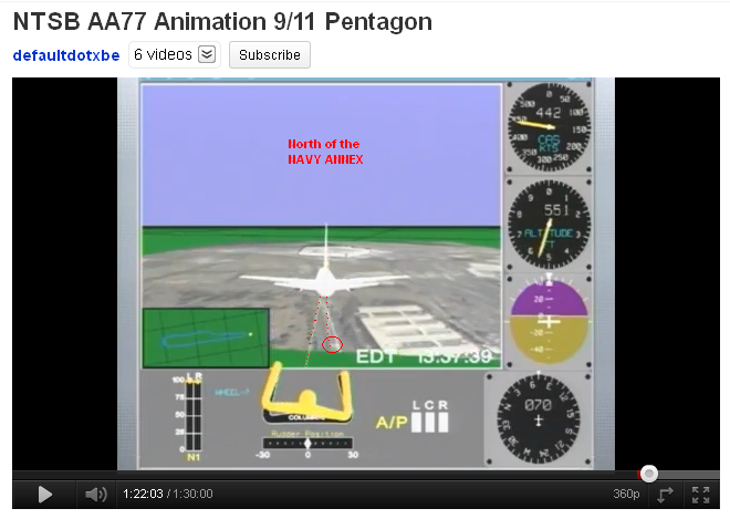
The NTSB animation, showing AA 77 flying 100 meters/yards NORTH of the northern rim of the Navy Annex buildings !!!!!!!!! :
www.abovetopsecret.com...
I thought the officially proposed heading was 60.25°, all the way on a straight flight path along the SOUTH side of the then eight Navy Annex buildings up to the point of impact.
And an awfull lot of witnesses talked about a 20 to 30° right bank turn flown by the plane.
Nothing to see of that in these last 20 NTSB animation seconds..... :
My Reheat and ProudBird rebuttal posts :
www.abovetopsecret.com...
www.abovetopsecret.com...
www.abovetopsecret.com...
My thorough explanation why Balsamo is wrong with his northern departure gate or another than D26 , and I am totally right about the real departure gate at Dulles International, namely the usual Gate D26, and I prove it in all these posts :
www.abovetopsecret.com...
www.abovetopsecret.com...
www.abovetopsecret.com...
www.abovetopsecret.com...
www.abovetopsecret.com...
www.abovetopsecret.com...
www.abovetopsecret.com...
www.abovetopsecret.com...
www.abovetopsecret.com...
Title : Official Story Shill Crushed By Truther/Researcher in Radio Debate!
At page 47, I give the final explanation of the probable exact flight path flown by AA 77 in the last 12 seconds :
www.abovetopsecret.com...
www.abovetopsecret.com...
www.abovetopsecret.com...
This is the final proposal :
www.abovetopsecret.com...
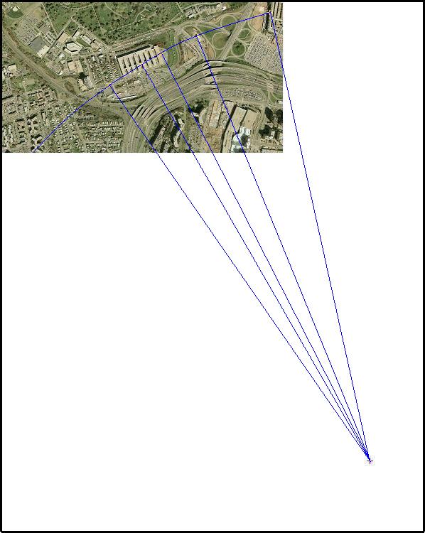
I based myself on the length of the Navy Annex building measured in Google Earth to be nearly exactly 300 meters (984.25 feet) in length, from wing 1 to wing 8. Then it is easy to see that the radius I drew in there, is nearly exactly 4 times as long, measured with a pair of compasses. That means my drawn turn radius is 3,200 meters long.
That's 10,498.7 feet.
Which is a FIVE times bigger arc radius, than Reheat used as the maximum arc radius (2000 feet) in his signature "NoC debunk piece" link.
And thus perfectly normal to perform, while the extremely tight turns for a passenger plane like the B757-200 he brought up are totally impossible to perform.
For even the casual reader of Reheat's sig-link it is obvious that that whole link does not contain ONE even remotely viable rebuttal of the NoC witnesses their reported positions and flight path for Flight AA 77.
So, why did he choose that title? He did not debunk one iota of that NoC thesis.
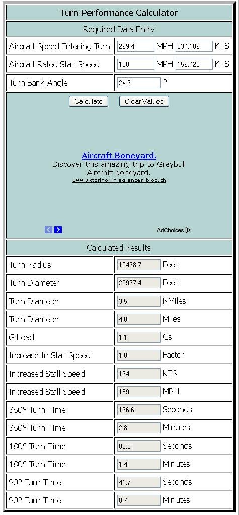
When you however fill in and tweak the online turn calculator he linked to, with some known and previously unknown data, like the following data, then the speed when entering that turn of 269.4 MPH (234.109 KTS) is what comes out when we enter the other parameters :
757-200 stall speed (by ProudBird) = 180 MPH (156.420 KTS)
(Note that the stall speed, or minimum flying speed, begins only to increase rapidly, beyond a bank angle of 60°, which corresponds to 2 g's.)
Turn Bank Angle = 24.9°
G Load = 1.1 Gs
We take a radius of turn of 10,498.7 feet (x 0.3048) = 3200 meters.
That's the radius drawn by me in the above viable AA 77 arc-picture.
Which covers all known NoC witnesses.
Note that the online calculator notes this :
Which we already did. The Boeing 757-200.
And when I observe the rounding off of the used values in this calculator, the approximation will be inside a less than a meter fault margin.
Post #38 is a very long list with highlighted parts of witness testimonies that indicate an overall very strong indication and feeling that the witnesses were describing a different flight path than the official story :
pilotsfor911truth.org...
ProudBirds Turn and Bank calculator, the same btw as Reheat's one that I used to show him he was wrong from his post here :
www.abovetopsecret.com...
www.csgnetwork.com...
Enter 434.5 KNOTS as the speed (500 MPH) and 180 MPH as the rated stall speed of a 757, and a 22° bank angle.
Enter 200 KNOTS as the speed (230.2 MPH) and the same two other inputs.
Quite a different radius, ain't it so?
41,548.3 feet at 500 MPH. (This one will only fit ONE witness position all the time, all you try)
8,806.9 feet at 230.2 MPH. (this one fits ALL 5 witness positions I used in this drawing by me, while Reheat keeps repeating that I drew a wrong radius, but in fact it is the radius he keeps throwing at me, 8,806.9 feet (about 2.7 km, 2.684 km) :
The NTSB animation, showing AA 77 flying 100 meters/yards NORTH of the northern rim of the Navy Annex buildings !!!!!!!!! :
www.abovetopsecret.com...
I thought the officially proposed heading was 60.25°, all the way on a straight flight path along the SOUTH side of the then eight Navy Annex buildings up to the point of impact.
And an awfull lot of witnesses talked about a 20 to 30° right bank turn flown by the plane.
Nothing to see of that in these last 20 NTSB animation seconds..... :
My Reheat and ProudBird rebuttal posts :
www.abovetopsecret.com...
www.abovetopsecret.com...
www.abovetopsecret.com...
My thorough explanation why Balsamo is wrong with his northern departure gate or another than D26 , and I am totally right about the real departure gate at Dulles International, namely the usual Gate D26, and I prove it in all these posts :
www.abovetopsecret.com...
www.abovetopsecret.com...
www.abovetopsecret.com...
www.abovetopsecret.com...
www.abovetopsecret.com...
www.abovetopsecret.com...
www.abovetopsecret.com...
www.abovetopsecret.com...
www.abovetopsecret.com...
Title : Official Story Shill Crushed By Truther/Researcher in Radio Debate!
At page 47, I give the final explanation of the probable exact flight path flown by AA 77 in the last 12 seconds :
www.abovetopsecret.com...
www.abovetopsecret.com...
www.abovetopsecret.com...
This is the final proposal :
www.abovetopsecret.com...
I based myself on the length of the Navy Annex building measured in Google Earth to be nearly exactly 300 meters (984.25 feet) in length, from wing 1 to wing 8. Then it is easy to see that the radius I drew in there, is nearly exactly 4 times as long, measured with a pair of compasses. That means my drawn turn radius is 3,200 meters long.
That's 10,498.7 feet.
Which is a FIVE times bigger arc radius, than Reheat used as the maximum arc radius (2000 feet) in his signature "NoC debunk piece" link.
And thus perfectly normal to perform, while the extremely tight turns for a passenger plane like the B757-200 he brought up are totally impossible to perform.
For even the casual reader of Reheat's sig-link it is obvious that that whole link does not contain ONE even remotely viable rebuttal of the NoC witnesses their reported positions and flight path for Flight AA 77.
So, why did he choose that title? He did not debunk one iota of that NoC thesis.
When you however fill in and tweak the online turn calculator he linked to, with some known and previously unknown data, like the following data, then the speed when entering that turn of 269.4 MPH (234.109 KTS) is what comes out when we enter the other parameters :
757-200 stall speed (by ProudBird) = 180 MPH (156.420 KTS)
(Note that the stall speed, or minimum flying speed, begins only to increase rapidly, beyond a bank angle of 60°, which corresponds to 2 g's.)
Turn Bank Angle = 24.9°
G Load = 1.1 Gs
We take a radius of turn of 10,498.7 feet (x 0.3048) = 3200 meters.
That's the radius drawn by me in the above viable AA 77 arc-picture.
Which covers all known NoC witnesses.
Note that the online calculator notes this :
All calculated values should be considered as approximate. Consult your aircraft manual for specific values for YOUR aircraft.
Which we already did. The Boeing 757-200.
And when I observe the rounding off of the used values in this calculator, the approximation will be inside a less than a meter fault margin.
This is a screenshot with those data fed into that turn performance calculator.
The right wing tip follows the blue arc. Robert Turcios placed the plane's right wing tip passing over the northeastern tree just beside the northern CITGO canopy and the filling pumps there.
Penny Elgas said she saw the plane's wing tip pass just over the CITGO roof and come right at her over Columbia Pike, which is making there a wide turn, to go further to the South Parking Lot. Penny stood a few cars behind the car where the plane passed over. Christine Peterson sat in her car while the plane came right over her. And she said she stood just in front of the Heli pad :
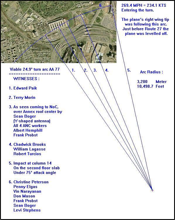
Which 24.9° light bank angle looks very much like what all of the Arlington National Cemetery witnesses showed in their CIT video interviews, as the right bank angle they witnessed when the plane descended in the direction of the ANC maintenance buildings grounds. By holding a small model plane up in their hand and showing us the bank angle, while it descended towards them.
And it looks very much like what Sean Boger described, this "Small bank angle" drawing from aerospaceweb.org, used by Reheat in his own calculations link, which they call a small, 51° right bank angle at 1.5 G, but Reheat calls it an aerobatic turn and bank for a 757 :
This below picture, with its lowest picture showing an airplane such as a 757-200 that would be turning while at a right bank angle of 42°, is a good example of a nearly double as high bank angle as the one I use above in my arc drawing, namely an 24.9° angle :
When the pilot, while in a f.ex. 42° right bank turn, does not pull his steering column up, but leaves it in the neutral position, the plane will also automatically descend while turning in that bank, just as AA77 did, when we may believe all the witnesses.
I really hope I am now saved from Reheat's annoying repetitive few-liner posts, that my final 3200 meter radius arc, showing a turn bank angle of 24.9°, is not viable, because he thinks that only a 50° to 60° bank angle would be the result of my shown arc, which flies over all NoC witnesses that were near or under Flight AA 77.
Or witnesses that looked at that passenger plane from behind it, beside it or head-on to it, while its nose cone was on its way to its Pentagon impact point. At column 14 (Y-axis, vertical) and the second floor slab (X-axis, horizontal) in the west wall. Which was 4.3 meters above the grass of the adjacent Pentagon lawn, according to the ASCE its Pentagon Building Performance Study (BPS) report :
Well, here it is, up there, my final proposal.
Posted on 25/12/2011 by me already, so who's the one with memory problems?
Did you forgot that post, or is it more convenient to act as if you indeed forgot it?
The right wing tip follows the blue arc. Robert Turcios placed the plane's right wing tip passing over the northeastern tree just beside the northern CITGO canopy and the filling pumps there.
Penny Elgas said she saw the plane's wing tip pass just over the CITGO roof and come right at her over Columbia Pike, which is making there a wide turn, to go further to the South Parking Lot. Penny stood a few cars behind the car where the plane passed over. Christine Peterson sat in her car while the plane came right over her. And she said she stood just in front of the Heli pad :
Which 24.9° light bank angle looks very much like what all of the Arlington National Cemetery witnesses showed in their CIT video interviews, as the right bank angle they witnessed when the plane descended in the direction of the ANC maintenance buildings grounds. By holding a small model plane up in their hand and showing us the bank angle, while it descended towards them.
And it looks very much like what Sean Boger described, this "Small bank angle" drawing from aerospaceweb.org, used by Reheat in his own calculations link, which they call a small, 51° right bank angle at 1.5 G, but Reheat calls it an aerobatic turn and bank for a 757 :
This below picture, with its lowest picture showing an airplane such as a 757-200 that would be turning while at a right bank angle of 42°, is a good example of a nearly double as high bank angle as the one I use above in my arc drawing, namely an 24.9° angle :
When the pilot, while in a f.ex. 42° right bank turn, does not pull his steering column up, but leaves it in the neutral position, the plane will also automatically descend while turning in that bank, just as AA77 did, when we may believe all the witnesses.
I really hope I am now saved from Reheat's annoying repetitive few-liner posts, that my final 3200 meter radius arc, showing a turn bank angle of 24.9°, is not viable, because he thinks that only a 50° to 60° bank angle would be the result of my shown arc, which flies over all NoC witnesses that were near or under Flight AA 77.
Or witnesses that looked at that passenger plane from behind it, beside it or head-on to it, while its nose cone was on its way to its Pentagon impact point. At column 14 (Y-axis, vertical) and the second floor slab (X-axis, horizontal) in the west wall. Which was 4.3 meters above the grass of the adjacent Pentagon lawn, according to the ASCE its Pentagon Building Performance Study (BPS) report :
All columns in the first story had square cross sections and spirally reinforced cores with a concrete cover of 1 1/2 in.,The story height was 14 ft 1 in.
Well, here it is, up there, my final proposal.
Posted on 25/12/2011 by me already, so who's the one with memory problems?
Did you forgot that post, or is it more convenient to act as if you indeed forgot it?
Over to another subject, also important for this SoC versus NoC issue.
Post by apathoid at JREF :
Post by apathoid at JREF :
Originally Posted by WilliamSeger.
I know you guys have discussed the AA77 FDR data here, so I thought this would be the best place to ask: The NTSB animation shows a magnetic heading of 070 just before hitting the Pentagon. Corrected by -10.5 degrees, that would be a true heading of 59.5. On the Democratic Underground September 11 forum, I posted a graphic of that heading (the same one that my friend Roger Harris has already posted here) showing how that heading would be over the bridge where the lamp posts were knocked down. (The point of the post was that Pilotsfor911truth still has the video up even after knowing that it showed an incorrect compass orientation.) JohnDoeX showed up, and among other things claimed that the FDR data from AA77 shows the plane was on a true course of 061.5, presumably because of wind. That's not much of a difference - and that course would still be over the bridge! - but is there any way to tell from the FDR data what the true course was?
Hi William. To answer your last question - I'm not sure but I dont think so. You'd have to look at a wind correction chart for the true track. AFAIK, the FDR doesnt record track, only heading.
Navigation jargon can be quite confusing, but what I think JDX is possibly referring to is "track", not course. The FDR would certainly record the course selector position, but that has no bearing (pun not intended) on the direction of flight. These three terms are sometimes interchanged but they mean completely differenet things:
Heading - Direction the nose is pointing
Course - Desired track along the ground
Track - Actual path along the ground
2.5 degrees of wind drift does seem a bit much for 465 kts against 10-12 kts of wind.
ETA: 2.5 degrees is too much. By plugging in wind direction, speed, airspeed and heading into this calculator - I got 1.0 degrees of wind correction angle. I used 330 degrees and 10 kts for the wind and I'm basing that on this weather report for National Airport at 0951 on 9/11/01. I used 465 kts for grounspeed and 70 degrees for the heading.
This post by ProudBird triggered my curiosity again :
I advice the reader to first read my answer to him, and then proceed to read here.
www.abovetopsecret.com...
And that's why I re-read this :
THE PENTAGON BUILDING PERFORMANCE STUDY (BPS) REPORT
ProudBird, your Graphics of note, pp 36, 37, 38 and 39, they ALL depict different angles than their own concluded 42° angled attack path for AA 77. So, that makes you wonder, ain't that so?
fire.nist.gov...
WARNING for JREF members : This report is considered a "wall of text" lately, in your circles, so we expect you, as usual, to not take the time to read it.
I think those of you reading my bolded, colored, but especially my underlined texts (and like me, have read thousands of dissertations, thesis and patents), will know directly, that these guys were seriously pissed off and managed to get these lines pushed through the end-editing process, resulting in this full paragraph's text, being allowed to stay in this form in this report.
Mlakar was the same Army Corps of Engineers career guy, who also led the Oklahoma City Bombing Report. Another skewed piece of disinformation, just as this one.
It's not all disinfo of course, that would it make too obvious, but its the small details that stick out, like all the plane drawings are not 42° angled attacks, they are all depicting bigger to much bigger angles of attack.
Because when they would have drawn the real 42° angle they decided on, it would have cut the generator trailer in half and obliterated that trailer totally, and ended far left from the column 14 entrance hole center line on and around the second floor slab.
Thus, not covering the internal damage path lined up as a 42° damage path by the Pentagon Building Performance Report members, at all.
That 42° angle was based by the ASCE team, on the center-line of damage, drawn from a few points between the 5 downed light poles, through the generator trailer AA 77 its wing-tip damage (the cabin roof gouge) and the internal damage path to that ridiculous "exit" hole.
When you reverse the process, and start a 42° angled line depicting the nose cone attached to the fuselage of AA 77, and draw that back from that ridiculous "exit" hole, through the internal damage path its center, as depicted in the ASCE report, and then forget for a moment that pesky trailer in the way, but then extend that line through the center of those 5 downed light poles, and THEN look back at that generator trailer, you see AA 77 its fuselage cut right through that trailer's left side.....
Another (BPS) Building Performance Study-team member from Purdue University, Mete Sozen, did put this animation on-line, which also shows a different than 42° attack flight path :
www.abovetopsecret.com...
This above link to a post written by me, offers about all there is to know about the generator its cabin-roof gouge, and the dishonest attack angles shown in the ASCE Report and the Purdue animations.
And it shows that the ASCE conclusion of a 42° attack angle would have resulted in a total miss of the photographed impact point, with about 60 meters, to the north of that real impact point in the west wall (Y-axis at column 14, X-axis at the second floor slab).
And should have formed a totally different gouge, namely a long diagonal gouge from the frontside right corner to the backside left corner in the roof of the generator cabin on that trailer in the outmost corner of the fenced-in portion of the Pentagon Renovation contractors and sub-contractors working area.
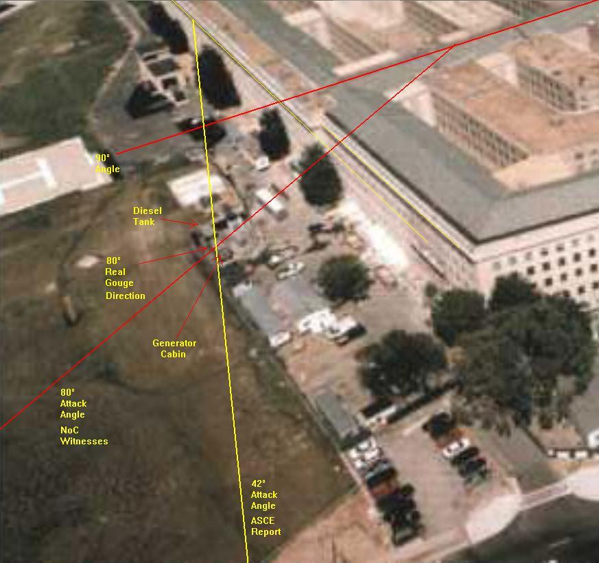
What we see however in the gouge photos, is a 62° gouge angle.
The Purdue University CGVLAB its Pentagon attack simulations animation using LS-DYNA Runs, made by Mete Sozen et al :
video.google.com/videoplay?docid=5506786479079283934
This above block of text from the same page 18 (of 45) shows also the hidden frustration that they could not inspect and collect samples of curious places, where a free researcher would see explosive damage. But in just 4 hrs CONTROLLED and LIMITED access, there was no chance in hell that these guys would be allowed to sample suspected portions of the building.
When I read the word "controlled" and "not comprehensive" in one report page, I can see the soldiers looking over the researcher's shoulder, leading him away from spots not allowed to inspect, and stopping him from any sample taking that did perhaps show high explosives evidence.
Page 19 :
Especially the word "extent" coupled to "impact" is very telling in this context.
Those team members expressed clearly with those two words, that they doubted and could not assume that all the internal damage they saw up to the "exit" hole in Ring C, was caused by the impact OF A PLANE. And especially not in the collapsed portion of Ring E, the west wall portion. It is also telling that they do not report that they were shown photographs or Army Corps of Engineers reports from the meticulous 25 days (9/11 to 10/03) cleansing of the collapsed portion of Wedge 1.(Corps of Engineers study, Paragraph 4.3)
I read this text, and for me it is as clear as glass, that these guys were very very frustrated.
And knew that they were used. To form the impression in all non-military readers of their report, that they did a good job. They however could NOT do a good and thorough job.
They were not allowed to do a thorough investigation.
Anyone who knows what it takes to perform a thorough structural research report of such an enormous debris site, laughs his nuts off when reading that these poor guys were ALLOWED in under CONTROLLED access rules for a measly 4 hours, and knows immediately that it was meant to be a con-job. And to fail any possible chance that there was other evidence to be found, like the use of explosives for example.
Or a totally different attack path.
The Army Corps of Engineers cleansed that site in the forgoing 25 days, and then these poor guys were allowed in for FOUR hours.
This ASCE report is written mainly on the basis of studying other parties reports.
Which were all paid by or worked for, or were in the Army.
6. DISCUSSION
There's reason to believe, that an outer third portion of the right wing must have been sheared off, after it hit the generator trailer roof. And that this event started the fires behind the Generator trailer.
The next quote from the ASCE's BPS report should be remembered when looking at my 80° to 90° impact path drawing that I made from this report's drawing that showed a plane that was entering the Pentagon under a supposed angle of 42°.
I just introduced another plane entering the same spot, but now at an angle of 90°.
And the nose of that 90° plane came no further than the full length of the original, not compacted plane. Which ends at about the Wedge 1 its first, Ring-E back side, shown as a thin red line in the original drawing. And yes, we know very well that the first two stories in the first three Rings were long office spaces, divided by thin brick or gypsum board walls only. And full of reinforced concrete columns that held up the higher floors.
Ask yourself another important question: "Do I think that any non-military first responders had a shimmer of a chance to ever get to a point in the building further than let's say the E-ring area, to witness any damage done further than that point? And to find any victims? See the Pentagon map drawing that I posted with the positions drawn-in, from the victims. Pentagon personnel and plane victims.
Do note the strange amount of victims in the NAVY offices, which laid not at all in the trajectory of a 42° angled plane, but were however straight in line with a 80° to 90° angled plane, that however did not get further than the first, Ring-E its backside perimeter line, according to the internal first floor column damage drawings.
That means the second floor slab began at a height of 4.30 meter above grade.
Originally posted by ProudBird
reply to post by LaBTop
.....I am convinced that an airplane smashed head-on into the huge concrete second floor slab above the ground floor at the west wall of the Pentagon.
Whew. (Wiping brow).
At a near 90° angle.
Oh? Then this is complete rubbish? All of the people involved lied, and continue to lie? Little bit difficult to reconcile, wouldn't you think?:
THE PENTAGON BUILDING PERFORMANCE REPORT
(Graphics of note, pp 36, 37, 38 and 39)
I advice the reader to first read my answer to him, and then proceed to read here.
www.abovetopsecret.com...
And that's why I re-read this :
THE PENTAGON BUILDING PERFORMANCE STUDY (BPS) REPORT
ProudBird, your Graphics of note, pp 36, 37, 38 and 39, they ALL depict different angles than their own concluded 42° angled attack path for AA 77. So, that makes you wonder, ain't that so?
fire.nist.gov...
WARNING for JREF members : This report is considered a "wall of text" lately, in your circles, so we expect you, as usual, to not take the time to read it.
5. BPS SITE INSPECTIONS
Members of the BPS team inspected the site on two occasions. Between September 14 and September 21, 2001, team leader Paul Mlakar had limited access to the site while rescue and recovery operations were still in progress. On this early inspection visit, he examined the exterior of the building and portions of the building interior.
Controlled access to the site was granted to the full team after rescue and recovery operations were complete. On October 4, 2001, the Pentagon team, together with John Durrant, the executive director of ASCE’s institutes, and W. Gene Corley, the BPS team leader at the World Trade Center, inspected the interior and exterior of the damaged area of the Pentagon for approximately FOUR hours.
The inspection of the BPS team focused on obvious physical damage, primarily in the region of the impact.This inspection was not comprehensive. It did not address fire damage to concrete as a material, and it did not result in full documentation of all physical damage or as-built construction.
By the time the full Pentagon BPS team visited the site, all debris from the aircraft and structural collapse had been removed (figure 5.1) and shoring was in place wherever there was severe structural damage. The design team charged with reconstructing the Pentagon was assessing the building and preparations were being made to demolish the areas for reconstruction. Consequently, the Pentagon BPS team never had direct access to the structural debris as it existed immediately after the aircraft impact and subsequent fire.
I think those of you reading my bolded, colored, but especially my underlined texts (and like me, have read thousands of dissertations, thesis and patents), will know directly, that these guys were seriously pissed off and managed to get these lines pushed through the end-editing process, resulting in this full paragraph's text, being allowed to stay in this form in this report.
Mlakar was the same Army Corps of Engineers career guy, who also led the Oklahoma City Bombing Report. Another skewed piece of disinformation, just as this one.
It's not all disinfo of course, that would it make too obvious, but its the small details that stick out, like all the plane drawings are not 42° angled attacks, they are all depicting bigger to much bigger angles of attack.
Because when they would have drawn the real 42° angle they decided on, it would have cut the generator trailer in half and obliterated that trailer totally, and ended far left from the column 14 entrance hole center line on and around the second floor slab.
Thus, not covering the internal damage path lined up as a 42° damage path by the Pentagon Building Performance Report members, at all.
That 42° angle was based by the ASCE team, on the center-line of damage, drawn from a few points between the 5 downed light poles, through the generator trailer AA 77 its wing-tip damage (the cabin roof gouge) and the internal damage path to that ridiculous "exit" hole.
When you reverse the process, and start a 42° angled line depicting the nose cone attached to the fuselage of AA 77, and draw that back from that ridiculous "exit" hole, through the internal damage path its center, as depicted in the ASCE report, and then forget for a moment that pesky trailer in the way, but then extend that line through the center of those 5 downed light poles, and THEN look back at that generator trailer, you see AA 77 its fuselage cut right through that trailer's left side.....
Another (BPS) Building Performance Study-team member from Purdue University, Mete Sozen, did put this animation on-line, which also shows a different than 42° attack flight path :
www.abovetopsecret.com...
This above link to a post written by me, offers about all there is to know about the generator its cabin-roof gouge, and the dishonest attack angles shown in the ASCE Report and the Purdue animations.
And it shows that the ASCE conclusion of a 42° attack angle would have resulted in a total miss of the photographed impact point, with about 60 meters, to the north of that real impact point in the west wall (Y-axis at column 14, X-axis at the second floor slab).
And should have formed a totally different gouge, namely a long diagonal gouge from the frontside right corner to the backside left corner in the roof of the generator cabin on that trailer in the outmost corner of the fenced-in portion of the Pentagon Renovation contractors and sub-contractors working area.
What we see however in the gouge photos, is a 62° gouge angle.
The Purdue University CGVLAB its Pentagon attack simulations animation using LS-DYNA Runs, made by Mete Sozen et al :
video.google.com/videoplay?docid=5506786479079283934
Google Video Link |
The teams attempted to inspect and photograph all columns with significant visible damage and most of the beams and floor bays with significant visible damage.To the extent possible, it was noted whether physical loads or the effects of fire caused the observed damage. The BPS team also noted the performance of windows and exterior wall reinforcements that had been installed to enhance blast resistance in Wedge 1 prior to the attack. However the BPS team inspections were not comprehensive, and they did not address fire-related material degradation.
This above block of text from the same page 18 (of 45) shows also the hidden frustration that they could not inspect and collect samples of curious places, where a free researcher would see explosive damage. But in just 4 hrs CONTROLLED and LIMITED access, there was no chance in hell that these guys would be allowed to sample suspected portions of the building.
When I read the word "controlled" and "not comprehensive" in one report page, I can see the soldiers looking over the researcher's shoulder, leading him away from spots not allowed to inspect, and stopping him from any sample taking that did perhaps show high explosives evidence.
Page 19 :
Since all debris was removed prior to the detailed inspection, the team was unable to determine specifically the level and extent of impact damage in this region of the building.
Especially the word "extent" coupled to "impact" is very telling in this context.
Those team members expressed clearly with those two words, that they doubted and could not assume that all the internal damage they saw up to the "exit" hole in Ring C, was caused by the impact OF A PLANE. And especially not in the collapsed portion of Ring E, the west wall portion. It is also telling that they do not report that they were shown photographs or Army Corps of Engineers reports from the meticulous 25 days (9/11 to 10/03) cleansing of the collapsed portion of Wedge 1.(Corps of Engineers study, Paragraph 4.3)
I read this text, and for me it is as clear as glass, that these guys were very very frustrated.
And knew that they were used. To form the impression in all non-military readers of their report, that they did a good job. They however could NOT do a good and thorough job.
They were not allowed to do a thorough investigation.
Anyone who knows what it takes to perform a thorough structural research report of such an enormous debris site, laughs his nuts off when reading that these poor guys were ALLOWED in under CONTROLLED access rules for a measly 4 hours, and knows immediately that it was meant to be a con-job. And to fail any possible chance that there was other evidence to be found, like the use of explosives for example.
Or a totally different attack path.
The Army Corps of Engineers cleansed that site in the forgoing 25 days, and then these poor guys were allowed in for FOUR hours.
This ASCE report is written mainly on the basis of studying other parties reports.
Which were all paid by or worked for, or were in the Army.
6. DISCUSSION
6.1 IMPACT DAMAGE
The site data indicate that the aircraft fuselage impacted the building at column line 14 at an angle of approximately 42 degrees to the normal to the face of the building, at or slightly below the second-story slab. Eyewitness accounts and photographs taken by a security camera suggest that the aircraft was flying on nearly a level path essentially at grade level for several hundred feet immediately prior to impact.
Gashes in the facade above the second-floor slab between column lines 18 and 20 to the south of the collapse area suggest that the aircraft had rolled slightly to the left as it entered the building.
The right wing was below the second-floor slab at the fuselage but above the second-floor slab at the tip, and the left wing struck the building entirely below the second-floor slab, to the north of column line 14.
The width of the severe damage to the west facade of the Pentagon was approximately 120 ft (from column lines 8 to 20). The projected width, perpendicular to the path of the aircraft, was approximately 90 ft, which is substantially less than the 125 ft wingspan of the aircraft (figure 6.1).
An examination of the area encompassed by extending the line of travel of the aircraft to the face of the building shows that there are no discrete marks on the building corresponding to the positions of the outer third of the right wing. The size and position of the actual opening in the facade of the building (from column line 8 to column line 18) indicate that no portion of the outer two-thirds of the right wing and no portion of the outer one-third of the left wing actually entered the building.
It is possible that less of the right wing than the left wing entered the building because the right wing struck the facade crossing the level of the second-floor slab.The strength of the second-floor slab in its own plane would have severed the right wing approximately at the location of the right engine. The left wing did not encounter a slab, so it penetrated more easily.
In any event, the evidence suggests that the tips of both wings did not make direct contact with the facade of the building and that portions of the wings might have been separated from the fuselage before the aircraft struck the building. This is consistent with eyewitness statements that the right wing struck a large generator before the aircraft struck the building and that the left engine struck a ground-level, external vent structure. It is possible that these impacts, which occurred not more than 100 ft before the nose of the aircraft struck the building, may have damaged the wings and caused debris to strike the Pentagon facade and the heliport control building.
The wing fuel tanks are located primarily within the inner half of the wings.The center of gravity of these tanks is approximately one-third of the wing length from the fuselage. Considering this tank position and the physical evidence of the length of each wing that could not have entered the building, it appears likely that not more than half of the fuel in the right wing could have entered the building. While the full volume of the left wing tank was within the portion of the wing that might have entered the building, some of the fuel from all tanks rebounded upon impact and contributed to the fireball. Only a portion of the fuel from the left and right wing tanks and the center fuselage tank actually entered the building.
The height of the damage to the facade of the building was much less than the height of the aircraft’s tail. At approximately 45 ft, the tail height was nearly as tall as the first four floors of the building. Obvious visible damage extended only over the lowest two floors, to approximately 25 ft above grade.
Damage to the first-floor columns is summarized in figures 6.2 and 6.3. In formulating opinions about columns in the collapse area, the BPS team interpreted photographs taken after impact and before collapse.
There's reason to believe, that an outer third portion of the right wing must have been sheared off, after it hit the generator trailer roof. And that this event started the fires behind the Generator trailer.
The next quote from the ASCE's BPS report should be remembered when looking at my 80° to 90° impact path drawing that I made from this report's drawing that showed a plane that was entering the Pentagon under a supposed angle of 42°.
I just introduced another plane entering the same spot, but now at an angle of 90°.
And the nose of that 90° plane came no further than the full length of the original, not compacted plane. Which ends at about the Wedge 1 its first, Ring-E back side, shown as a thin red line in the original drawing. And yes, we know very well that the first two stories in the first three Rings were long office spaces, divided by thin brick or gypsum board walls only. And full of reinforced concrete columns that held up the higher floors.
More likely, the fuselage was destroyed much earlier in its movement through the building. Therefore, the aircraft frame most certainly was destroyed before it had traveled a distance that approximately equaled the length of the aircraft.
The debris that traveled the farthest, traveled approximately twice the length of the aircraft, after entering the building. To come to rest at a point 310 ft (figure 6.6) from the area of impact at a speed of 780 ft/s, that debris experienced an average deceleration of approximately 30 g.
Ask yourself another important question: "Do I think that any non-military first responders had a shimmer of a chance to ever get to a point in the building further than let's say the E-ring area, to witness any damage done further than that point? And to find any victims? See the Pentagon map drawing that I posted with the positions drawn-in, from the victims. Pentagon personnel and plane victims.
Do note the strange amount of victims in the NAVY offices, which laid not at all in the trajectory of a 42° angled plane, but were however straight in line with a 80° to 90° angled plane, that however did not get further than the first, Ring-E its backside perimeter line, according to the internal first floor column damage drawings.
All columns in the first story had square cross sections and spirally reinforced cores with a concrete cover of 1 1/2 in.,The story height was 14 ft 1 in.
That means the second floor slab began at a height of 4.30 meter above grade.
Originally posted by LaBTop
Show me your calculations to refute mine, not your avoidance of the subject by hoping the reader will believe your online credibility.
I showed you my calculations for my turn radius, do us a favor and show me were I made a miscalculation in my above post.
You can't, because it's perfectly right calculated.
With an error margin of 7 meters on a radius of 3200 meter....... Can you do better ?
Thought it might be a laugh to try. Here's my interpretation of your picture (can you please provide a higher-res one or preferably some coordinates?)

Chord length is 1176m
Sagitta length is 86m
(Google Earth measurements)
radius = 1176²/8*86 + 86/2
radius = 43 + 1176²/688
radius = 2053m
Your radius is 1150m too large according to the diagram I can extrapolate from your low resolution image. If you'd like to pick more accurate spots I can recalculate.
This also increases the predicted bank angle (using the same, allegedly incorrect values) to 35.9°
Feel free to present your rebuttal, I look forward to it.
Originally posted by Reheat
Originally posted by LaBTop
Any contra-arguments?edit on 8/6/12 by LaBTop because: (no reason given)
Yea, your turn radius is about % 40 too large.
I still have no clue how on earth you come to that conclusion.
I used my pair of compasses, my ruler and the 200 meter/500 feet ruler at the bottom of my SoC last radar return photo.
I blew up all the photos I used to the max, and then measured the distances.
You can't make it more precise.
Enlighten me with a peek in your brain, when working at peak calculating power. Type it...! Draw it..! Post it..!
Or do you dodge the meat of the matter again, as usual?
That 24.9° bank angle is by far not an impossible big bank angle, it is a very slight one.
As described by all witnesses in the path of the plane as a slightly banking plane.
Your repeated writing that my turn radius of 3200 meter or 10,498 feet, needs an impossible huge bank angle is contradicted by your own online turn calculator.
Or do you imply that this screenshot of my turn and bank calculation, using your own linked-to calculator, is giving faulty data?
Try to be honest, are you bluntly trying to dodge my invitation to show YOUR own turn calculation of MY "viable 24.9° bank turn" drawing and my posted calculations and the methods I used and posted to find the distances involved?
As I showed you now and many times before, that I take immense amounts of time to explain why I think AA 77 flew NoC and impacted at column 14.
You however just type one or, at the most a few minutes, and then ....WHAT? Laughing your belly off, every time I try to give you an as good as possible constructed answer, that obviously must have cost me a mountain of time and lots of research.
reply to post by exponent
Yes, that is very close to my own calculations. In fact, considering the resolution yours and mine are within a few meters of each other. However, you're dealing with a hard head that won't listen...
I'm finished until he determines where his measurements are wrong. Let him post his walls of text and see how much good it does for anything other than his ego...
edit on 8-6-2012 by Reheat because: (no reason given)
edit on 8-6-2012 by Reheat because: (no reason
given)
Originally posted by Reheat
reply to post by exponent
Yes, that is very close to my own calculations. In fact, considering the resolution yours and mine are within a few meters of each other. However, you're dealing with a hard head that won't listen...
I'm finished until he determines where his measurements are wrong. Let him post his walls of text and see how much good it does for anything other than his ego...edit on 8-6-2012 by Reheat because: (no reason given)edit on 8-6-2012 by Reheat because: (no reason given)
Yeah he's clearly just spamming this thread with endless post after post so that anyone even attempting to address it has to decipher that huge mess first.
I don't really know where I would even begin, other than to alert the mods and get them to ask labtop to repost one bit at a time.
reply to post by exponent
One would think by now since he gets so few responses that he'd realize most folks don't even bother to read the crap.. The English is so poor with adverbs out of place much of it is near impossible to decipher. Oh well, some people have an obsession that is not understandable. I stopped trying to understand long ago...
Thanks for doing the calculations. Maybe, just maybe he'll eventually realize he's "out to lunch" and will find another hobby to obsess about...
reply to post by exponent
Thank you, at last one who cares to explain the problem I seem to have caused to myself.
Reheat, when you would have done that a year ago, we would have avoided a lot of misunderstandings and would have spared me a lot of wasted time.
Exponent, I admit your method is better and more exact than what I used.
Can you print your arc line also?
I would like to use your method on your hires aerial photo, since I think the plane's last recorded position as the NTSB reported it, is where we should start the chord. Not where you started it, on the lip of Edward Paik.
And that would be on the other side of the street, the southern side of Columbia Pike, at a spot opposite of the southern facade of the Sheraton.
The NTSB gave that as the last fully recorded position in the last fully written block of AA 77's FDR.
And that resulting arc should run just north of the CITGO roof, and end at column 14.
Remember that on 9/11 there was another 8th Annex Wing standing on the nowadays remaining parking lot.
I still think we can find an acceptable arc radius, and that arc would cover most of the witness positions.
And have an acceptable shallow bank angle.
I first have to master Google Earth again. Or you could do it, as you offered already.
You know what I aim at, cover as many of the interviewed CIT witnesses positions as possibly can, with a turn radius arc that results in an acceptable bank angle when fed in that turn calculator..
A bank angle that is about what those 4 ANC workers showed in their CIT videos.
I also just found out that my blue arc does not originate from my center point. My bad.
I admit I was using a wrong arc, offset from my center point.
I checked it again with my PoC's, and saw that when I use my center, the arc in fact runs more downward at the left side. Strange, that I never saw that before. I really thought I had double-checked the arc before posting.
That is caused by me using a cropped photo inside a Paint window, and in Paint I can't draw that part of a circle that is my proposed arc, from that center point.
I hope I can still construct also a viable arc with a shallow bank angle, that covers all witnesses I included.
With my method, but now used on printed material, so I am not hindered by the shortcomings of my simple Paint program. Then I will scan it in again, and post it, if it delivers a viable arc.
An arc is just part of a circle, so it would not be so difficult to do it the old-fashioned way I am used to.
That way I can make a drawing as big as I want.
Hehe, at last IMPROVEMENT.
reply to post by LaBTop
This is just what I expected. Rather than admit to a gross error that I told you about several months if not a year ago you attempt to evade responsibility and now admit to an error in your calculations that you've been denying for approximately a year apparently because you think you're smarter than everyone else...
Exponent DID NOT tell you how he did the calculations he just posted the result same as I did a long time ago.
Although you elude to the arc as you're problem that wasn't it at all. Both exponent and I were using the exact same arc that you used. You simply miscalculated the radius primarily because as I've told you previously, you don't know what you're doing... You're trying to invent a conspiracy where none exists...
So, now you want to move the begin point across the street, do you? What you don't realize yet is that won't make an appreciable difference in the radius. It will be a very small amount.
I'm going to tell you one more time. You CAN NOT get away from the large bank angle that NO ONE witnessed. No one mentioned it at all. That bank angle must be held all of the way to impact. You can invent double inverted rat's ass maneuvers if you want, but that won't help you at all. It is an aerodynamic fact that the bank angle calculated must fit the arc or be greater in order to fly an equal to or a smaller arc. That only compounds your problem of trying desperately to make this work...
Also, you will still need to use an unreasonably slow speed when most of the witnesses said it was haulin' ass. But true to form you choose what will fit your fairy tale that are outlier statements made by a couple of witnesses. That's known as "cherry picking" information.
You can't see the forest for the trees and continue to try to invent irrational crap that is ultimately preposterous when the bulk of the evidence is staring you right in the face.
Honest truther my derriere. You are like the vast majority of all of the rest. The refusal to accept responsibility, to admit and and apologize for mistakes and come to your senses are hallmarks of trutherdom...
You need to find another hobby, this one is a failure for you...
Originally posted by LaBTop
Exponent, I admit your method is better and more exact than what I used.
Can you print your arc line also?
I'm not sure that is so easy inside Google Earth. I had to manually work on the yellow lines to ensure that the sagitta was at 90° to the chord. I'll see if I can find a better method at some point.
I would like to use your method on your hires aerial photo, since I think the plane's last recorded position as the NTSB reported it, is where we should start the chord. Not where you started it, on the lip of Edward Paik.
Please give me exact coordinates, the last recorded point I know of is
38°51'46.55"N
77° 4'39.83"W
Please also post the exact impact point you want. Using Google Earth may make some measurements inaccurate due to the terrain. I'll see what I can do about producing a solver that just overlays the solution on a kml. No promises though.
You know what I aim at, cover as many of the interviewed CIT witnesses positions as possibly can, with a turn radius arc that results in an acceptable bank angle when fed in that turn calculator..
A bank angle that is about what those 4 ANC workers showed in their CIT videos.
I don't believe that such a thing is possible without artificially lowering the speed of AA77 beyond reasonable levels. Bear in mind that at the moment within a few seconds you've had the plane slow by almost 200 knots.
I don't think I'll be able to meet your criteria, because I don't think they're possible. If you want me to try though you will have to specify exact coordinates for each point, so that I can not be accused of manipulating data.
This further below, former John Farmer or Warren Stutt FDR based positional flight path map is at this Australian website link :
The Science of 9/11
A SCIENTIFIC STUDY of the best HARD EVIDENCE
scienceof911.com.au...
That last sentence I contest. He said in another interview that it was banking when he first saw it, with one of its wings up.
I also contest the last sentence of the whole page,
See my Watergate thread where I proved to my own surprise that Gate D26 which was the gate where AA 77 always departed when flying from Dulles, was also still the real 9/11 departure gate.
Balsamo and CIT still seem to disbelieve it at their Pilotsfor911Truth forums, while I gave indisputable evidence, nota bene based primarily on fine work first done by one of their own members, tumetufaisdubien.
The Science of 9/11
A SCIENTIFIC STUDY of the best HARD EVIDENCE
scienceof911.com.au...
New decoding of FDR file.
The new decoding of the Flight Data Recorder (FDR), done by Warren Stutt, shows that there were 4 more seconds of data at the end of the file, previously not decoded. He thus confirms the work of John Farmer, who used radar records to show that several seconds of data had to be missing from the version of the FDR file initially available. More recently (2009) John has provided details of the process he went through to establish the time of impact from radar data in his “ Time Normalization ” paper.
Warren managed to decode the last section of the FDR file and we now see that the data describes a plane descending smoothly, pulling up safely and hitting the Pentagon near the ground, as so many eyewitnesses have reported. The impact time from the FDR agrees with the radar data to within 3 seconds.
Here is a convenient summary of some findings pertaining to the flight and its last moments. It includes the entire testimony of Penny Elgas who watched the impact and reported that a piece of the plane fell into her car, probably though the open sunroof.
The track set out in the FDR file corresponds closely with the track derived from the radar data. Radar cannot give accurate information near the ground and the FDR file previously had data missing from the end, hence there was a narrow window of opportunity for controversy.
...........................MAP...................................
Flight path as shown by the FDR and the damage trail
Above is an image of the area from the Navy Annex to the Pentagon. The yellow line is the track established by the trail of damage through the light poles and inside the Pentagon, the angle of which is confirmed by the FDR file and the radar tracks from four separate facilities. This is set out in a peer reviewd paper at the Journal of 9/11 Studies, AA77 on 9/11: New FDR Analysis.
The green line is the line of sight of Albert Hemphill from his vantage point high in the Navy Annex to the impact point on the Pentagon. You can see that the line passes over the Citgo service station. Hemphill repeatedly asserted in interviews and in statements that the plane passed over his right shoulder and dived straight over the bridge (the overpass of VA27 across Columbia Pike) hitting a light pole, and impacting the Pentagon. “It didn’t pull up, it didn’t turn right, it didn’t turn left. It went right into the Pentagon”. If it didn’t turn, it went straight. That is a pretty indisputable concept, yet some dispute it. Clearly his view of the plane at impact passed over Citgo but the plane did not.
That last sentence I contest. He said in another interview that it was banking when he first saw it, with one of its wings up.
I also contest the last sentence of the whole page,
Clearly there is no case to be made that the FDR file can show from which gate the plane departed.
See my Watergate thread where I proved to my own surprise that Gate D26 which was the gate where AA 77 always departed when flying from Dulles, was also still the real 9/11 departure gate.
Balsamo and CIT still seem to disbelieve it at their Pilotsfor911Truth forums, while I gave indisputable evidence, nota bene based primarily on fine work first done by one of their own members, tumetufaisdubien.
I copied and then altered that originally by Farmer or Stutt made, FDR its flight path positions and its radio-heights combined with internal damage
trail map, and it can be found here, in my ATS pictures map :
files.abovetopsecret.com...
A by Farmer or Stutt made, "Flight path as shown by the FDR and the damage trail", altered by me, LaBTop to show the real paths and the real impact point, and show the real extended from the internal damage trail, extrapolated 42° attack path. Which is NOT the 52° FDR plotted path, not by far!
Shift all paths downwards, the same distance as that between my corrected impact point to their wrong impact point !
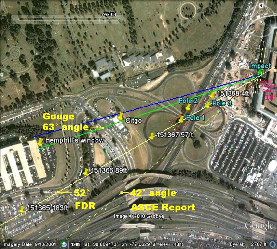
First, this above map once drawn by John Farmer, who also decoded the FOIA freed FDR data and used the lat. and long. data and the radio heights from 1 second FDR data blocks in his map (the yellow 52° FDR line with GE pins) is why I still am firmly convinced that the last part of that FDR is falsified, and that the end speeds and positional data and probably also the radio heights data extracted from that FDR are maliciously wrong.
It seems that we have to go back in that FDR to a point where the speed is between 270 and 300 MpH. After that, all the data frames and blocks of that FDR must have been altered.
Why? Because only a much slower speed of AA 77 at the end, will fit an acceptable right bank as seen by so many NoC flight path witnesses.
36 Seconds before impact seem to be that spot in the FDR, there suddenly the thrust levers were set to full power, see that "AA77, Engine Parameters" figure in this already provided link : scienceof911.com.au...
The airspeed before that was about 310 KTS
.
IMPORTANT REMARKS regarding the original drawing by John Farmer :
1. The impact point shown in this John Farmer made Google map is wrong, it ends at the building expansion joints between Wedge 1 and 2, the spot where Wedge 1 after about 20 minutes after impact, broke down and collapsed. I gave the real impact point in red at column 14 in my altered Farmer-map version above.
It means that I should have shifted all lines that same distance downwards, but that would have made a mess from that map, so I opted to let you imagine that line shift yourself.
So all drawn attack-lines must be shifted down the distance between the green GE-pin Farmer placed at his wrong impact point, and my new red real impact point at column 14.
This is especially important for the green 63° Gouge angle alias "Hemphill point of view" green same line, which is also nearly the 62° generator trailer roof gouge angle of 62° I calculated. When shifted down, it re-affirms Hemphills remark that he saw the plane for the first time out of the corner of his eye come flying over the Annex roof, over his right shoulder. After that impact point shift, that new path fits this drawing and his position (yellow pin) exactly. Now the plane comes flying over the roof beside his right shoulder.
It's 62° attack angle path does not fit anything in the officially pushed SoC flight path.
NOR the FIVE DOWNED and CUT LIGHT-POLES
2. This shown by me, thin yellow attack angle line of 42° touted by ASCE as based on the internal damage path in the Pentagon, derived as a line from the "Exit" hole in the C-Ring wall towards the Entrance hole in the facade of the outer E-Ring, exactly at column 14 and at the second floor slab, does not fit the NoC witnesses statements at all.
NOR the FIVE DOWNED and CUT LIGHT-POLES
3. The shown by yellow Google Earth pins FDR decoded attack angle of 52° by John Farmer in the original map he made, is accepted by the NTSB, FAA, RADES and NORAD as being extracted from what they assume to be a true FDR, but does not fit at all the NoC witnesses. Nor the ASCE internal damage trail path angle of 42°.
NOR the FIVE DOWNED and CUT LIGHT-POLES
files.abovetopsecret.com...
A by Farmer or Stutt made, "Flight path as shown by the FDR and the damage trail", altered by me, LaBTop to show the real paths and the real impact point, and show the real extended from the internal damage trail, extrapolated 42° attack path. Which is NOT the 52° FDR plotted path, not by far!
Shift all paths downwards, the same distance as that between my corrected impact point to their wrong impact point !
First, this above map once drawn by John Farmer, who also decoded the FOIA freed FDR data and used the lat. and long. data and the radio heights from 1 second FDR data blocks in his map (the yellow 52° FDR line with GE pins) is why I still am firmly convinced that the last part of that FDR is falsified, and that the end speeds and positional data and probably also the radio heights data extracted from that FDR are maliciously wrong.
It seems that we have to go back in that FDR to a point where the speed is between 270 and 300 MpH. After that, all the data frames and blocks of that FDR must have been altered.
Why? Because only a much slower speed of AA 77 at the end, will fit an acceptable right bank as seen by so many NoC flight path witnesses.
36 Seconds before impact seem to be that spot in the FDR, there suddenly the thrust levers were set to full power, see that "AA77, Engine Parameters" figure in this already provided link : scienceof911.com.au...
The airspeed before that was about 310 KTS
.
IMPORTANT REMARKS regarding the original drawing by John Farmer :
1. The impact point shown in this John Farmer made Google map is wrong, it ends at the building expansion joints between Wedge 1 and 2, the spot where Wedge 1 after about 20 minutes after impact, broke down and collapsed. I gave the real impact point in red at column 14 in my altered Farmer-map version above.
It means that I should have shifted all lines that same distance downwards, but that would have made a mess from that map, so I opted to let you imagine that line shift yourself.
So all drawn attack-lines must be shifted down the distance between the green GE-pin Farmer placed at his wrong impact point, and my new red real impact point at column 14.
This is especially important for the green 63° Gouge angle alias "Hemphill point of view" green same line, which is also nearly the 62° generator trailer roof gouge angle of 62° I calculated. When shifted down, it re-affirms Hemphills remark that he saw the plane for the first time out of the corner of his eye come flying over the Annex roof, over his right shoulder. After that impact point shift, that new path fits this drawing and his position (yellow pin) exactly. Now the plane comes flying over the roof beside his right shoulder.
It's 62° attack angle path does not fit anything in the officially pushed SoC flight path.
NOR the FIVE DOWNED and CUT LIGHT-POLES
2. This shown by me, thin yellow attack angle line of 42° touted by ASCE as based on the internal damage path in the Pentagon, derived as a line from the "Exit" hole in the C-Ring wall towards the Entrance hole in the facade of the outer E-Ring, exactly at column 14 and at the second floor slab, does not fit the NoC witnesses statements at all.
NOR the FIVE DOWNED and CUT LIGHT-POLES
3. The shown by yellow Google Earth pins FDR decoded attack angle of 52° by John Farmer in the original map he made, is accepted by the NTSB, FAA, RADES and NORAD as being extracted from what they assume to be a true FDR, but does not fit at all the NoC witnesses. Nor the ASCE internal damage trail path angle of 42°.
NOR the FIVE DOWNED and CUT LIGHT-POLES
edit on 12/6/12 by LaBTop because: Added for all 3 path texts NOR the FIVE DOWNED and CUT LIGHT-POLES
Reheat, I admit that I was making an important measuring error.
I should have thoroughly double checked my method after you pointed out that it was faulty.
It turns out however that we still can arrive at a small bank angle of 35.9° when we assume that the plane flew much slower, at 234 KTS (269 MPH).
When one beliefs the NoC witnesses videos made by CIT, then that plane MUST have flown a lot slower than the FDR data offer.
I have now checked the whitish roof lengths of the 8 Wings of the original 9/11 Navy Annex to be 285 meters, in a 09/07/2001 historical Google Earth map. That's a 15 meters on 300 meters fault margin made in my calculations in my lowres map inside my blank Paint window which I placed the centerpoint of the circle which my drawn arc made part of. I used 300 meters, and now it's clear that it should have been 285 meters.
You however did never ever offer your radius calculation method which you used to check my numbers, and that made me think that you tried to make a fool of me, and stopped me from really seriously checking my drawn arc and its radius in a much bigger GE map.
My bad. Should have kept a cool mind, instead of falling for psychological tricks.
The method to compare the length of the Navy Annex with the radius is precise enough when all maps are being enlarged enough and are hi-res ones. Mine was low-res.....
However, if that Annex length is measured correct it works, which it was not.
That radius looked to me to be really 3207 meters long, based on a 300 meter length of the Navy Annex, which length I however should have double checked by using the measurement tool in Google Earth. That length I now re-measured was faulty by many meters. Or that 200 meter/500 feet GE left bottom placed scale in my posted Google Earth SoC radar return point map must be far out of reality.
I measured the Navy Annex its whitish 8 roofs their total length, so including the then still existing 8th Wing roof, as being 300 meters long. It is however 285 meters long.
And then used the same Navy Annex roofs length measured by my PoC's in my map, repeatedly over the radius I drew in my map. That Annex length from my map covered my radius in that same map 10.69 times.
I now recalculated it more precise, and the radius from my wrong centerpoint to the impact point was 3051 meters, when using a presumed Annex length of 300 meters.
(Annex length 2.05 cm, wrong radius length 20.85 cm = 10.17 x 300 m = 3051 m)
I now remeasured that real radius in my below new map with the real centerpoint, and found these figures :
Northern Annex roofs length included Wing 8 is 2.05 cm,
The right radius length from real centerpoint as printed in this corrected new map is :
20.90 cm, so I use 10.195 x 300 m = 3058.5 m.
So, my measure of the Annex roofs length was far from real.
The right way is : 10.195 x 285 m = 2,905.575 meters length of that radius.
Exponent, can you find an error in my above method?
If not, then the discrepancy between the outcome of my new map-measuring-method and your formula-method :
namely 2,905.575 - 2053 = 852.5 meters, seems so far from logical, that we have to re-evaluate both methods, to find the culprit.
I expect however it's in my far too roughly detailed map.
But still, such a huge error?
How come? My measure of the Annex was only 15 m on 300 m wrong which is a 5% error. Or a 5.26% error when an extra 15m on 285 m is considered.
But a 852.5 m on 2905.6 m error is a 29.35% error in total, which is illogical.
Or is the error accumulated by me when fitting the Annex roofs length X-times in that radius? About 7 times is the error multiplied then. One original Annex length error plus 6 more errors of about 5% added up every time I take that 285 m length over on the radius on my map. And that sums up to 1995 meters in total, while you found 2053 meters, so there must be some more minor errors slipped in while measuring with a PoC's.
Also, 7 x 300 m = 2100 m, while 7 x 285 = 1995 m, so the max accumulated error lays quite nice on top of the error margin, while your formula radius length of 2053 m is quite nice in between that error margin situated.
I think I solved that puzzle.
Do you agree, or do you have a better honed error-margin calc-version?
It looks that the line measuring feature of GE beats the old-school PoC's method.
At least if used on such an old unsharp aerial map like that one from Desmoulins I used.
When used on a modern GE map, the two methods will not differ much, I expect.
Supertankers still use PoC's, and round the world sailors still too. But they are glad they have GPS too....
One thing I found is that the normal Google Earth map that is loaded first when I click Pentagon, Washington D.C., District of Columbia, United
States, its camera angle gets severely distorted when I am going to move around with the map.
Btw, I first loaded a historical map from date 09/07/2001, then began to shift to the impact point which is pinned with the text "Opening Ceremony for September 11th Memorial".
I suppose it is the place on the former column 14 where the plane impacted, and is remembered by a plaquette inserted in the limestone plates, of a granite plate with text.
Then I went back to the Annex, measured its length which is 285 meters, and went back to the generator trailer's begin of its roof gouge, and the distance from that to the impact point pin was 37 meters.
Then I tried to find a correction setting to set the angle of photo shot exactly on 90°, thus straight to the center of the earth, and found that to be listed under "reset" in the third options column "Image" and then the "Reset" option, then click the "Overturn and Compass" option.
The whole scene began severely shifting northwards until it came to rest exactly above the map. You could now see that the original setting I was left with, after quite some moving around in the map and shifting the map itself in all directions, was very distorted, and this new one was perfect perpendicular to the ground.
It did not make a difference in chord or sagitta length measured.
However, I did not draw a chord first, and then used the overturn and compass function.
I drew a chord first that was a duplo from Exponent's chord, and found the same value in meters as he did. I should have repeat it after correction. Will do when have time.
My 07-09--2001 historical snapshot GE-map, the clean map I started with, only a 1182 meters long chord is already drawn in, stretching from a spot in front of Edward Paik's office on the street, named Columbia Pike, to the impact point plaquette on the present, 2012 Pentagon west wall.
Anyone can use this map to construct their own viable turn-arc with, just choose a sagitta length that fit your ideas about the NoC flight path flown by AA 77.
It must be placed perpendicular to the center of that chord I already drew, and lead the resulting arc over the CITGO canopy, or better, to fit the 2 Pentagon Police officers remarks, fully north of that canopy :
External full URL link : files.abovetopsecret.com...
CLEAN GE-MAP :
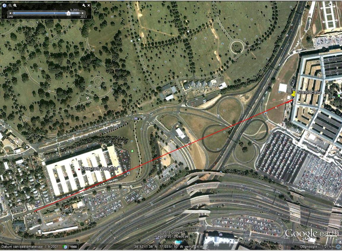
The next map is the ultimate map I made, with the same chord but with a sagitta of 100 meter, instead of 86 meters, which was the one drawn by Exponent.
I then measured the same chord length as you used, from Paik's office window to impact at column 14, and found that to be 1182 meters. Which is 6 meters more than your 1176 meters. Neglectable. One slight move of the mouse away from a spot on the Pike in front of the pin "A-One Auto-Clinic" (text can be read when full map-expansion settings are being used) :
ARC-EXAMPLE GE-MAP :
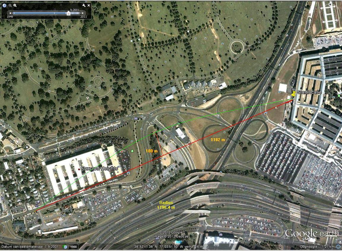
External full URL link: files.abovetopsecret.com...
So, the problem probably must be the result of my much rougher measuring with an aluminum ruler of the cm's in my corrected AA77ViableTurnArc drawing.
I drew a sagitta length in my above 07/09/2001 clean GE-map, and as a result the turn radius that the plane's right wing-tip flew along this resulting arc becomes :
radius = (sagitta squared) + (1/2 length of chord squared) divided by 2 x sagitta.
(100x100) + (591x591) / 2x100 = 10,000 + 349,281 / 200 = 359,281 / 200 = 1796.4 m.
This radius fed in the online turn calculator gives a still considered as small, bank angle of 41.8°.
I filled the calculator in with 280 MPH /243.320 KTS, Stall Speed 180 MPH / 156.420 KTS and then a 41.8° Turn bank Angle gives a radius of 5888.9 feet which is 1795 meters.
Sufficiently near that calculated needed radius of 1796.4 meters to say that a plane flying at a small bank angle of 41.8° will follow that, drawn by me, green colored arc, with its right wing tip.
I still say that the arc you drew using my initial speed of 234.109 KTS / 269.4 MPH when entering the turn, filling in a given by ProudBird B757-200 stall speed of about 180 MPH / 156.420 KTS (Reheat shouts softly in the background that it is 160 KTS), which delivered a turn radius of 2053 meters with a 35.9° turn bank angle is still a small bank angle, according to pilots. And a 41.8° bank angle also.
And that's all I wanted to show the readers, that such a small bank flown in a slight right banked arc was in practice possible for AA 77 when entering that turn in front of Edward Paik's office window.
But only at about half the FDR end speed of nearly 500 KTS, which could have been the above 234.320 to 243.320 KTS.
Another problem also was, that my arc was not drawn as a circ
Btw, I first loaded a historical map from date 09/07/2001, then began to shift to the impact point which is pinned with the text "Opening Ceremony for September 11th Memorial".
I suppose it is the place on the former column 14 where the plane impacted, and is remembered by a plaquette inserted in the limestone plates, of a granite plate with text.
Then I went back to the Annex, measured its length which is 285 meters, and went back to the generator trailer's begin of its roof gouge, and the distance from that to the impact point pin was 37 meters.
Then I tried to find a correction setting to set the angle of photo shot exactly on 90°, thus straight to the center of the earth, and found that to be listed under "reset" in the third options column "Image" and then the "Reset" option, then click the "Overturn and Compass" option.
The whole scene began severely shifting northwards until it came to rest exactly above the map. You could now see that the original setting I was left with, after quite some moving around in the map and shifting the map itself in all directions, was very distorted, and this new one was perfect perpendicular to the ground.
It did not make a difference in chord or sagitta length measured.
However, I did not draw a chord first, and then used the overturn and compass function.
I drew a chord first that was a duplo from Exponent's chord, and found the same value in meters as he did. I should have repeat it after correction. Will do when have time.
My 07-09--2001 historical snapshot GE-map, the clean map I started with, only a 1182 meters long chord is already drawn in, stretching from a spot in front of Edward Paik's office on the street, named Columbia Pike, to the impact point plaquette on the present, 2012 Pentagon west wall.
Anyone can use this map to construct their own viable turn-arc with, just choose a sagitta length that fit your ideas about the NoC flight path flown by AA 77.
It must be placed perpendicular to the center of that chord I already drew, and lead the resulting arc over the CITGO canopy, or better, to fit the 2 Pentagon Police officers remarks, fully north of that canopy :
External full URL link : files.abovetopsecret.com...
CLEAN GE-MAP :
The next map is the ultimate map I made, with the same chord but with a sagitta of 100 meter, instead of 86 meters, which was the one drawn by Exponent.
I then measured the same chord length as you used, from Paik's office window to impact at column 14, and found that to be 1182 meters. Which is 6 meters more than your 1176 meters. Neglectable. One slight move of the mouse away from a spot on the Pike in front of the pin "A-One Auto-Clinic" (text can be read when full map-expansion settings are being used) :
ARC-EXAMPLE GE-MAP :
External full URL link: files.abovetopsecret.com...
So, the problem probably must be the result of my much rougher measuring with an aluminum ruler of the cm's in my corrected AA77ViableTurnArc drawing.
I drew a sagitta length in my above 07/09/2001 clean GE-map, and as a result the turn radius that the plane's right wing-tip flew along this resulting arc becomes :
radius = (sagitta squared) + (1/2 length of chord squared) divided by 2 x sagitta.
(100x100) + (591x591) / 2x100 = 10,000 + 349,281 / 200 = 359,281 / 200 = 1796.4 m.
This radius fed in the online turn calculator gives a still considered as small, bank angle of 41.8°.
I filled the calculator in with 280 MPH /243.320 KTS, Stall Speed 180 MPH / 156.420 KTS and then a 41.8° Turn bank Angle gives a radius of 5888.9 feet which is 1795 meters.
Sufficiently near that calculated needed radius of 1796.4 meters to say that a plane flying at a small bank angle of 41.8° will follow that, drawn by me, green colored arc, with its right wing tip.
I still say that the arc you drew using my initial speed of 234.109 KTS / 269.4 MPH when entering the turn, filling in a given by ProudBird B757-200 stall speed of about 180 MPH / 156.420 KTS (Reheat shouts softly in the background that it is 160 KTS), which delivered a turn radius of 2053 meters with a 35.9° turn bank angle is still a small bank angle, according to pilots. And a 41.8° bank angle also.
And that's all I wanted to show the readers, that such a small bank flown in a slight right banked arc was in practice possible for AA 77 when entering that turn in front of Edward Paik's office window.
But only at about half the FDR end speed of nearly 500 KTS, which could have been the above 234.320 to 243.320 KTS.
Another problem also was, that my arc was not drawn as a circ
Another problem also was, that my arc was not drawn as a circle with that centerpoint I provided in the same map, i.o.w. the circle center point did
not fit my drawn arc ...that should have given me a serious warning, when I had seen that earlier.
It turns out however, that it makes only a 7.5 meter difference in the radius, which is very small on a presumed but wrong length of 3058.5 meters.
This is the same map, but now with the real centerpoint belonging to the arc I drew through all NoC witnesses. I also gave the pixel coordinates from Paint, so anyone can use those for a rough estimation of distances, since we know the dots per inch ratio.
I only do not know if dots equal pixels in Paint.
If so, the length of my map is 13.55 cm : 2.54 = 5.335 inch.
Resolution of my map is 96 x 96 dots / inch
Height x width of my new real center map = 810 x 646 pixels.
MAP with real centerpoint.
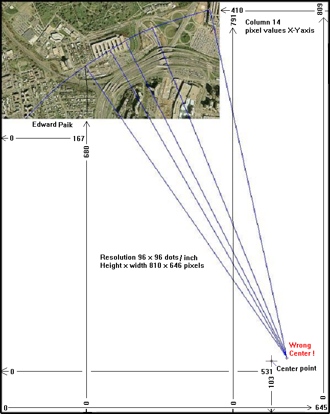
As exponent showed me, the radius of that arc must be 2053 meters.
And not 3207 meters which I calculated wrong.
It turns out however, that it makes only a 7.5 meter difference in the radius, which is very small on a presumed but wrong length of 3058.5 meters.
This is the same map, but now with the real centerpoint belonging to the arc I drew through all NoC witnesses. I also gave the pixel coordinates from Paint, so anyone can use those for a rough estimation of distances, since we know the dots per inch ratio.
I only do not know if dots equal pixels in Paint.
If so, the length of my map is 13.55 cm : 2.54 = 5.335 inch.
Resolution of my map is 96 x 96 dots / inch
Height x width of my new real center map = 810 x 646 pixels.
MAP with real centerpoint.
As exponent showed me, the radius of that arc must be 2053 meters.
And not 3207 meters which I calculated wrong.
new topics
-
Comparing the theology of Paul and Hebrews
Religion, Faith, And Theology: 25 minutes ago -
Pentagon acknowledges secret UFO project, the Kona Blue program | Vargas Reports
Aliens and UFOs: 1 hours ago -
Boston Dynamics say Farewell to Atlas
Science & Technology: 1 hours ago -
I hate dreaming
Rant: 2 hours ago -
Man sets himself on fire outside Donald Trump trial
Mainstream News: 4 hours ago -
Biden says little kids flip him the bird all the time.
2024 Elections: 4 hours ago -
The Democrats Take Control the House - Look what happened while you were sleeping
US Political Madness: 4 hours ago -
Sheetz facing racial discrimination lawsuit for considering criminal history in hiring
Social Issues and Civil Unrest: 4 hours ago -
In an Historic First, In N Out Burger Permanently Closes a Location
Mainstream News: 6 hours ago -
MH370 Again....
Disaster Conspiracies: 7 hours ago
top topics
-
In an Historic First, In N Out Burger Permanently Closes a Location
Mainstream News: 6 hours ago, 14 flags -
The Democrats Take Control the House - Look what happened while you were sleeping
US Political Madness: 4 hours ago, 11 flags -
Thousands Of Young Ukrainian Men Trying To Flee The Country To Avoid Conscription And The War
Other Current Events: 17 hours ago, 8 flags -
A man of the people
Medical Issues & Conspiracies: 12 hours ago, 8 flags -
Man sets himself on fire outside Donald Trump trial
Mainstream News: 4 hours ago, 7 flags -
Biden says little kids flip him the bird all the time.
2024 Elections: 4 hours ago, 6 flags -
4 plans of US elites to defeat Russia
New World Order: 14 hours ago, 4 flags -
Pentagon acknowledges secret UFO project, the Kona Blue program | Vargas Reports
Aliens and UFOs: 1 hours ago, 4 flags -
Sheetz facing racial discrimination lawsuit for considering criminal history in hiring
Social Issues and Civil Unrest: 4 hours ago, 3 flags -
Are you ready for the return of Jesus Christ? Have you been cleansed by His blood?
Religion, Faith, And Theology: 9 hours ago, 3 flags
active topics
-
The Democrats Take Control the House - Look what happened while you were sleeping
US Political Madness • 40 • : ImagoDei -
Thousands Of Young Ukrainian Men Trying To Flee The Country To Avoid Conscription And The War
Other Current Events • 39 • : RickyD -
12 jurors selected in Trump criminal trial
US Political Madness • 109 • : ImagoDei -
Boston Dynamics say Farewell to Atlas
Science & Technology • 2 • : theatreboy -
The defamation of Mary Magdalene
Religion, Faith, And Theology • 15 • : Solvedit -
A man of the people
Medical Issues & Conspiracies • 9 • : tarantulabite1 -
Silent Moments --In Memory of Beloved Member TDDA
Short Stories • 47 • : Naftalin -
George Knapp AMA on DI
Area 51 and other Facilities • 28 • : theshadowknows -
Pentagon acknowledges secret UFO project, the Kona Blue program | Vargas Reports
Aliens and UFOs • 4 • : Ophiuchus1 -
Comparing the theology of Paul and Hebrews
Religion, Faith, And Theology • 0 • : DISRAELI2