It looks like you're using an Ad Blocker.
Please white-list or disable AboveTopSecret.com in your ad-blocking tool.
Thank you.
Some features of ATS will be disabled while you continue to use an ad-blocker.

Can This Configuration Generate a Current from a Constant Magnetic Flux?
page: 1share:
This idea looks at the shape of the iron bar, that is the conduit for the magnetic flux. What if the iron bar within a coil, is either widening or
tapering?
My thinking here is that as an iron bar becomes wider/thicker, you might expect the strength of the magnetic flux at the surface of the bar to drop due to the fact that a constant level of flux energy is now moving thru a larger area of iron, that also has a larger circumference. So if that's the case, then if you had a copper coil around the expanding section of iron bar, then the flux strength at the point of contact with the first turn of the coil would be greater than at the point of contact with the 2nd turn which is greater than at the point of contact with the 3rd turn, etc. It seems to me that this is precisely what happens when you have a increasing magnetic flux passing thru an iron bar/coil of constant thickness. For a fraction of a second, one part of the coil is in contact with iron that has a higher flux strength versus another part of the coil. Is it this imbalance of forces that imparts the current, which in turn allows the coil to generate it's own magnetic field that must in some way balance the unequal points of flux strength?
I'll be attaching a hand drawn diagram sometime in the next few days.
If there's a flaw in my theory, based on empirical evidence, then I'd like to hear it.
If someone can test my theory, I'd like to hear the results of that too. I'm putting this idea into the public domain. If it works, anyone can use it.
edit on 15-10-2011 by Studenofhistory because: Not finished posting
hi op
just a quick glance
your never going to get a constant
but its an interesting thought
hope to see your diagrams
just a quick glance
your never going to get a constant
but its an interesting thought
hope to see your diagrams
reply to post by davesmart
Not sure what you mean by not getting a constant. If a permanent magnet generates a constant level of magnetic flux, then my theory should work. I've read that flux from magnets does fluctuate slightly most of the time which is not a problem that I can see. As long as the flux at the point of contact with the coil, is different at different points of contact, then a current should be induced regardless of whether it's because of an iron bar that's either expanding or tapering in width/thickness OR due to fluctuating magnetic flux.
Not sure what you mean by not getting a constant. If a permanent magnet generates a constant level of magnetic flux, then my theory should work. I've read that flux from magnets does fluctuate slightly most of the time which is not a problem that I can see. As long as the flux at the point of contact with the coil, is different at different points of contact, then a current should be induced regardless of whether it's because of an iron bar that's either expanding or tapering in width/thickness OR due to fluctuating magnetic flux.
reply to post by Studenofhistory
A magnetic circuit behaves like an electrical circuit and what you propose is introducing a section of higher impedance in a series circuit. What will happen is the overall flow of magnetic flux will be reduced in the entire circuit so there won't be any imbalance such as the one you're hoping for.
Nature always seeks equilibrium.
EDIT: the hypothesis can easily be tested with a couple of coils & permanent magnets plus a few pieces of ferrous material to act as armatures to concentrate the flux and make 1 coil experience roughly twice the flux density present at the other coil. I predict that the net output of the 2 coils will be zero once the circuit has stabilised because EM induction requires movement of the magnetic field in relation to the conductor. Stationary field plus stationary conductors = 0 induction.
I made a small diagram of the arrangement but ATS image uploads are currently disabled?
edit on 16/10/2011 by Pilgrum because: (no reason given)
reply to post by Studenofhistory
Current is generated in a conductor during a change in magnetic field. Your configuration will not have a changing magnetic field.
Current is generated in a conductor during a change in magnetic field. Your configuration will not have a changing magnetic field.
reply to post by Pilgrum
First of all, I disagree with your assertion that a magnetic circuit acts like an electrical circuit. When you combine two magnets in parallel, you get four times the flux strength due to the Force Square Law(google Flynn's parallel path). If you combine two electric currents, you do not get four times the amps/volts/watts.
Second, you'd be right if in fact the flux strength at any point of contact between the iron bar and the copper coil remains constant but what I'm proposing is that the geometry of an iron bar that is either widening or tapering, will effectively change flux strength at the surface of the iron bar. So far, no one has given me a valid explanation of why this would not be the case.
That is false. If you combine two electric currents, you do indeed get 4 times the watts.
Originally posted by Studenofhistory
First of all, I disagree with your assertion that a magnetic circuit acts like an electrical circuit. When you combine two magnets in parallel, you get four times the flux strength due to the Force Square Law(google Flynn's parallel path). If you combine two electric currents, you do not get four times the amps/volts/watts.
Power is equal to the square of the current times resistance. So if you double the current, you get four times the power (watts).
www.electronics-tutorials.com...
P = I * I * R that is, power equals the current squared times the resistance.
And the previous posters are correct in stating that your device won't generate a current, but why not build it yourself and confirm it if you doubt them? The reason I won't build it is I already know the outcome, but if I was unsure of the outcome like you seem to be, then I would build it and test it, it sounds pretty easy to build and test. However, your time initially may be better spent learning the fundamentals of electromagnetism which you don't seem to be familiar with.
Pteridine did.
So far, no one has given me a valid explanation of why this would not be the case.
Did you try the link at "Tools, ATS uploads"? It's a new link, the old link says it's temporarily disabled, but I think it's probably permanent.
Originally posted by Pilgrum
I made a small diagram of the arrangement but ATS image uploads are currently disabled?
edit on 16-10-2011 by Arbitrageur because:
clarification
Ummmmm please close this thread. Its crazy talk. Good try though. Glad to see somebody thinking outside the box. Next time understand the rules that
created the box to begin with. Good try though. Close this, do some studying, and try again.
Im not putting you down. I to made the same mistakes in the beginning. Lol wait till you try to cheat entropy. Hahahaha
Im not putting you down. I to made the same mistakes in the beginning. Lol wait till you try to cheat entropy. Hahahaha
Tried the new uploads feature but I guess it has a few bugs to be sorted out - the image is only 158x113 pixels and less than 5kB but I don't get any
icon displayed after uploading (attempted upload 3 times with no error messages). It's painfully slow too to the point where my browser just gives
up on loading the page which could be the problem or part of it.
OP: there is a good analogy between electrical and magnetic circuits and what you propose is making a section of that magnetic circuit a higher impedance than the rest. In designing high frequency magnetics for switchmode power supplies we use small airgaps to do just that and thus control the flux density to avoid saturation by increasing the impedance (lowering the permeability to be precise). It's exactly the same as inserting a higher value resistor in a series circuit and the entire series circuit experiences the lower 'flow'.
OP: there is a good analogy between electrical and magnetic circuits and what you propose is making a section of that magnetic circuit a higher impedance than the rest. In designing high frequency magnetics for switchmode power supplies we use small airgaps to do just that and thus control the flux density to avoid saturation by increasing the impedance (lowering the permeability to be precise). It's exactly the same as inserting a higher value resistor in a series circuit and the entire series circuit experiences the lower 'flow'.
Here's the little pic I made of the arrangement to test the idea:
Finally got the 'upload' thing to work but only by using IE8 so this could be my last upload here (I could die of old age waiting for IE8 to load a page).
The forked armature can be made of anything ferrous such as scrap fencing wire. Coil B has roughly twice the flux in its core compared to coil A if identical magnets are used. Try the coils individually, in series, in parallel and see what outputs can be detected.
I wouldn't go spending too much on the experiment though
reply to post by Pilgrum
I think there was a problem with the image uploads today, I tried it earlier and it wasn't working for me either. I just tried it again, with Firefox 7 and it worked fine. It must have just been a glitch earlier, and no need to use IE8. Your version of Flash needs to be reasonably up to date though I think.
Your prediction about what will happen with that experiment is correct.
I believe somebody else already mentioned that there is no change in the magnetic field in this diagram which means no generation of electricity.
However, you may get a very tiny amount of electricity on a humid day due to the use of dissimilar metals.
However, you may get a very tiny amount of electricity on a humid day due to the use of dissimilar metals.
reply to post by Arbitrageur
Excuse me...do you understand basic math? Power (ie. watts) is equivalent to magnetic flux strength. There is an exponential gain when you connect two or more magnets in parallel. You do NOT get any exponential gain in watts, when you combine two or more sources of electric power either in parallel or in series. When I used the word 'current' I meant it in it's most general sense, not as amps or volts but rather watts. Watts is what counts. If you could get 4 times as much watts by combining two electric circuits in parallel, then the world's energy crisis would have been solved a long time ago.
As far as the notion that only a change in emf can induce a current, here is a direct quote from a physics textbook.
"The induced EMF is equal to the rate of change of magnetic flux linking the circuit."
So when we're talking about a circuit that's a coil wrapped around an iron core, the change in magnetic flux has to be the flux density on the surface of the iron core where the circuit(coil) touches it and the 'linking the circuit' part has to do with both end of the coil. So my concept matches this definition because I'm theorizing that the flux density at the surface of the iron core, will be different at one end of the coil as compared to the other end IF the section of core in the coil is either widening or shrinking.
As for testing this theory myself...I don't have the equipment, the parts(where do you go to find an iron bar that's either widening or tapering?), or the experience in soddering connections, etc.
reply to post by Pilgrum
Interesting configuration but according to the Force Square Law, that Joseph Flynn makes use of in his Parallel Path technology, the strength of the flux passing Coil B should be 4 times the strength of each magnet individually. This exponential gain is very intriguing especially if you substitute electro-magnets for the permanent magnets and then have the electro-magnets powered by a coil that taps into the exponential gain in flux. It then becomes a self-powering and maybe even self-oscillating device. My concept involving a changing geometry of the iron core does not require the Force Square Law.
Interesting configuration but according to the Force Square Law, that Joseph Flynn makes use of in his Parallel Path technology, the strength of the flux passing Coil B should be 4 times the strength of each magnet individually. This exponential gain is very intriguing especially if you substitute electro-magnets for the permanent magnets and then have the electro-magnets powered by a coil that taps into the exponential gain in flux. It then becomes a self-powering and maybe even self-oscillating device. My concept involving a changing geometry of the iron core does not require the Force Square Law.
reply to post by Studenofhistory
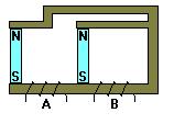
The closest analogy for what I think you're proposing is a 'venturi effect' and what you'll get is an increase in flux density within the narrowed section due only to the narrowed cross-section compared to the rest of the magnetic circuit which has a larger cross-sectional area. Very much akin to a sacrificial element in an electrical circuit (the fuse) where a narrowed cross-section piece will experienced sufficient current density to melt it at a defined current flow in order to protect the rest of the circuit from overheating. Total flux flow will remain the same through the entire magnetic circuit though and, with a static field, there'll be no relative flux/conductor movement and therefore no induced voltage as a result. Inserting and removing the magnet will produce momentary voltage spikes proportional to the rate of magnet movement but you're supplying the energy for that by moving the magnet.
You won't need any fabricating skills to prove this, just a permanent magnet, a few pieces of steel fence wire or some large nails and some thin insulated wire (eg telephone wire) for the coil will do. And a multimeter of course to prove the non-output nature of it all.
Here's a simple test setup:

The section B is a single piece of ferrous material while the rest of the magnetic circuit is 'doubled up' creating the section with twice the flux density of the rest of circuit between the magnet poles. Under static conditions there'll be no induced voltage but sliding the coil may induce a measurable voltage due to the magnetic 'venturi'.
The closest analogy for what I think you're proposing is a 'venturi effect' and what you'll get is an increase in flux density within the narrowed section due only to the narrowed cross-section compared to the rest of the magnetic circuit which has a larger cross-sectional area. Very much akin to a sacrificial element in an electrical circuit (the fuse) where a narrowed cross-section piece will experienced sufficient current density to melt it at a defined current flow in order to protect the rest of the circuit from overheating. Total flux flow will remain the same through the entire magnetic circuit though and, with a static field, there'll be no relative flux/conductor movement and therefore no induced voltage as a result. Inserting and removing the magnet will produce momentary voltage spikes proportional to the rate of magnet movement but you're supplying the energy for that by moving the magnet.
You won't need any fabricating skills to prove this, just a permanent magnet, a few pieces of steel fence wire or some large nails and some thin insulated wire (eg telephone wire) for the coil will do. And a multimeter of course to prove the non-output nature of it all.
Here's a simple test setup:
The section B is a single piece of ferrous material while the rest of the magnetic circuit is 'doubled up' creating the section with twice the flux density of the rest of circuit between the magnet poles. Under static conditions there'll be no induced voltage but sliding the coil may induce a measurable voltage due to the magnetic 'venturi'.
The word current has a meaning if you are referring to electric current:
Originally posted by Studenofhistory
reply to post by Arbitrageur
Excuse me...do you understand basic math? Power (ie. watts) is equivalent to magnetic flux strength. There is an exponential gain when you connect two or more magnets in parallel. You do NOT get any exponential gain in watts, when you combine two or more sources of electric power either in parallel or in series. When I used the word 'current' I meant it in it's most general sense, not as amps or volts but rather watts.
So very specifically current is indeed amps. If you want people to understand what you are talking about, you can't say that you meant watts when you said current because current means amps, not watts. It's not ambiguous or "general" as you put it, it's a specific term with a specific well-defined meaning. You need to learn the terminology and use it accurately f you wish to effectively communicate with others.
Electric current is a flow of electric charge through a medium.[1] This charge is typically carried by moving electrons in a conductor such as wire....
The SI unit for measuring the rate of flow of electric charge is the ampere.
Yes I gave you the math, power in watts is the current squared timed the resistance. You haven't given me any sources to prove this is wrong, and I gave you a source showing it's right. So you're claiming that you believe in a version of reality which you have failed to support with any sources. Doubling the current does indeed quadruple the watts, and if you don't understand this than it is you who don't know the math. I know it quite well thank you. And no unfortunately P=IxIxR hasn't solved world energy problems, why do you think it would?
Watts is what counts. If you could get 4 times as much watts by combining two electric circuits in parallel, then the world's energy crisis would have been solved a long time ago. Excuse me...do you understand basic math?
It's not giving you something for nothing, that's just the mathematical relationship between watts and amps versus resistance.
Again you fail to understand some very basic terminology. In this case, you don't know what "rate of change" means. Can you write this expression mathematically? That's why electrical engineers use a lot of math, because it's a much more precise language than English.
"The induced EMF is equal to the rate of change of magnetic flux linking the circuit."
...So my concept matches this definition because I'm theorizing that the flux density at the surface of the iron core, will be different at one end of the coil as compared to the other end IF the section of core in the coil is either widening or shrinking.
When you write out the math, does rate of change refer to the change per unit distance, or the change per unit time?
200.105.152.242...
From page 980, second paragraph:
Did you catch that?
Experiments conducted by Michael Faraday in England in 1831 and independently
by Joseph Henry in the United States that same year showed that an emf
can be induced in a circuit by a changing magnetic field. As we shall see, an emf
(and therefore a current as well) can be induced in many ways—for instance, by
moving a closed loop of wire into a region where a magnetic field exists. The results
of these experiments led to a very basic and important law of electromagnetism
known as Faraday’s law of induction. This law states that the magnitude of the
emf induced in a circuit equals the time rate of change of the magnetic flux
through the circuit.
It's "time rate of change".
And that answers your question, since you have nothing changing over time.
I hope that helps.
edit on 22-10-2011 by Arbitrageur because: clarification
reply to post by Arbitrageur
So if I understand you correctly, you're saying that if you combine two wires(in parallel), each of which is carrying 10 amps and 10 volts (100 watts each), the combined output will be 400 watts? Really? If that's the case, then the Earth's energy problems are solved! We just have to generate a small amount of electricty in two or more circuits, connected in parallel, and keep combining them to get this wonderful exponential gain out of nowhere!
What I think happens in the above example is that you get a combined flow of 10 amps with 20 volts = 200 watts and since the amps haven't changed, there is not effect from the formula you posted.
reply to post by Studenofhistory
Maybe you're getting confused about the difference between power dissipation and power transfer.
Your example of 2 wires each carrying 10A with 10V drop on each implies the wires have a resistance of 1 ohm (R=E/I) so each does dissipate 100W of heat, 200W total for the 2 parallel wires. With a single 1 ohm wire carrying the same total 20A, the voltage drop will be increased to (I.R) which is 20V and the total power then dissipated I^2.R or 20^2 x 1 = 400W.
If that's what you were getting at IE power dissipated is proportional to the square of the current while voltage drop is directly proportional to current.
Seems we're getting into interpretive semantics though but let's assume the total applied voltage is 110V so the current of 20A represents 2200W of power being delivered in which case the 400W lost in the 1 ohm cable impedance is only 18% of the supplied energy so 1800W of the total supplied 2200W is being transferred. Doubling up the cable cross-sectional area reduces the cable losses to 200W allowing 2000W to be transferred to the load.
Your narrowed section of magnetic circuit is directly analagous to this electrical example.
.
edit on 4/11/2011 by Pilgrum because: (no reason given)
Studenofhistory:
What you really get with a parallel circuit is a combined flow of 20 amps with 10 volts = 200 watts.
Pilgrum:
If you are simplifying his parallel circuit you would have a single .5 ohm wire carrying the same total 20A, the voltage drop is still 10v and the total power then dissipated I^2.R or 20^2 x .5 = 200W.
I think that is some of the confusion between you guys. Hope this helps out.
new topics
-
This is our Story
General Entertainment: 2 hours ago -
President BIDEN Vows to Make Americans Pay More Federal Taxes in 2025 - Political Suicide.
2024 Elections: 4 hours ago -
Ode to Artemis
General Chit Chat: 5 hours ago -
Ditching physical money
History: 8 hours ago -
One Flame Throwing Robot Dog for Christmas Please!
Weaponry: 8 hours ago -
Don't take advantage of people just because it seems easy it will backfire
Rant: 9 hours ago -
VirginOfGrand says hello
Introductions: 10 hours ago -
Should Biden Replace Harris With AOC On the 2024 Democrat Ticket?
2024 Elections: 10 hours ago
top topics
-
University student disciplined after saying veganism is wrong and gender fluidity is stupid
Education and Media: 13 hours ago, 12 flags -
Police clash with St George’s Day protesters at central London rally
Social Issues and Civil Unrest: 16 hours ago, 9 flags -
President BIDEN Vows to Make Americans Pay More Federal Taxes in 2025 - Political Suicide.
2024 Elections: 4 hours ago, 9 flags -
TLDR post about ATS and why I love it and hope we all stay together somewhere
General Chit Chat: 16 hours ago, 7 flags -
Should Biden Replace Harris With AOC On the 2024 Democrat Ticket?
2024 Elections: 10 hours ago, 6 flags -
Don't take advantage of people just because it seems easy it will backfire
Rant: 9 hours ago, 4 flags -
One Flame Throwing Robot Dog for Christmas Please!
Weaponry: 8 hours ago, 4 flags -
God lived as a Devil Dog.
Short Stories: 14 hours ago, 3 flags -
Ditching physical money
History: 8 hours ago, 3 flags -
VirginOfGrand says hello
Introductions: 10 hours ago, 2 flags
active topics
-
One Flame Throwing Robot Dog for Christmas Please!
Weaponry • 7 • : OzBiker -
University student disciplined after saying veganism is wrong and gender fluidity is stupid
Education and Media • 26 • : DerBeobachter2 -
President BIDEN Vows to Make Americans Pay More Federal Taxes in 2025 - Political Suicide.
2024 Elections • 4 • : 727Sky -
British TV Presenter Refuses To Use Guest's Preferred Pronouns
Education and Media • 128 • : Consvoli -
Terrifying Encounters With The Black Eyed Kids
Paranormal Studies • 70 • : burritocat -
Tucker Carlson UFOs are piloted by spiritual entities with bases under the ocean and the ground
Aliens and UFOs • 42 • : Jukiodone -
The Fight for Election Integrity Continues -- Audits, Criminal Investigations, Legislative Reform
2024 Elections • 4143 • : Station27 -
-@TH3WH17ERABB17- -Q- ---TIME TO SHOW THE WORLD--- -Part- --44--
Dissecting Disinformation • 636 • : F2d5thCavv2 -
Russia Ukraine Update Thread - part 3
World War Three • 5719 • : F2d5thCavv2 -
Who guards the guards
US Political Madness • 5 • : 19Bones79