It looks like you're using an Ad Blocker.
Please white-list or disable AboveTopSecret.com in your ad-blocking tool.
Thank you.
Some features of ATS will be disabled while you continue to use an ad-blocker.

The NIST report, start to finish
page: 10share:
Originally posted by psikeyhackr
Simplification would mean the 60 foot truss was just bent down at the middle 45 inches with two straight 30 foot lengths. So the arcsin of 45/360 = 7.18 degrees The cosine of 7.18 deg is 99.2.
Ah my mistake, I thought you were actually calculating force. Sorry about that
Originally posted by Azp420
This report proved nothing. I was forced to read the entire thing due to the poorly written abstract. It was basically six pages of them showing graphs and saying this is what our model produced, take our word that it is correct.
Isn't that exactly the same as all simulation reports? What exactly do you expect them to do other than show you the input and output of their models?
There are two very obvious problem with their model. They are claiming the tensile forces in the bottom chord became too much for it when the top chord was also working in compression to help support the loading and the bottom chord yielded. The top chord is then claimed to take over, somehow (no explanation given in the report) supporting the loading all on its own in an incredible catenary tensile manor that keeps angular deflection to only 11.6 degrees.
(correction included)
I don't see how this is a problem with their model at all. Truss dynamics are pretty clear, once sufficient element breakages occur the upper chord will inevitably slip into tension. Furthermore your quote of 11.6 degrees is given from your calculation of a figure I gave on a previous page, not this paper at all.
What is this massive tensile force keeping angular deflection to only 11.6 degrees? According to the graph from the report which you included in your post, a measly 85kN (rough eyeball from graph). So if 85kN is the horizontal component of this 11.6 degree catenary action, what is the value of the vertical component?
tan(11.6) x 85 = 17.4kN.
17.4kN? Isn't that a bit ridiculous?
It would be if 11.6 was referred to in the paper. Furthermore, if you were to look at your calculation you would realise that it predicts 0 vertical load with a flat truss.
There was a lot more discussion after this point, but nobody seems to have noticed that 11.6 degrees is based on your calculations of my example of deflection, not of any actual scenario.
In fact, given that we can estimate the horizontal reaction and the mass applied, we know it can only be produced through tension forces, and so you can work out the angle of the interaction with the wall and the total sag from just these values.
I've been super busy with work over the last few days, so I will return to this thread soon. I really hope I don't have to go providing mathematical proof as I am pretty ignorant still. We can probably approximate this closely enough with a parabola.
Originally posted by -PLB-
the word "most" should be "part". Although the question is how much this is really an error. It doesn't state that this situation is actually reached, just that it progresses towards it (I think the truss will indeed fail before it reaches that situation).
Azp's point was that the bolt connections would fail first, and this is not a new idea. How do you think failure at the bolts before exerting a significant "pull" force on the column would play in to NIST's hypothesis?
Originally posted by bsbray11
Is that for real? First time I've seen it.
They really think lightweight sagging trusses could rip the columns away like that?
That is not even the weak point of the system.
What's even worse is people actually believe that really happened.
Originally posted by ANOK
Originally posted by bsbray11
Is that for real? First time I've seen it.
They really think lightweight sagging trusses could rip the columns away like that?
That is not even the weak point of the system.
What's even worse is people actually believe that really happened.
That is what 80% of this rubbish is though it is not usually as obvious and stupid as that.
People have decided to BELIEVE that airliners could destroy the buildings and then proceed to RATIONALIZE BACKWARDS to how it could have happened. Time and physics run forward however. So we need accurate data on the initial conditions and then run the physics forward. That is what computer simulations are SUPPOSED TO DO.
But we seem to have a lot of data missing about these buildings. So the believers focus on the floor and trusses outside of the core. The horizontal beams that were in the core kind of disappeared.
But in the case of the south tower the plane only hit slightly above the mechanical floors on 76 and 77. So how could the collapsing floors push down the mechanical ones anyway?
psik
edit on 27-4-2011 by psikeyhackr because: (no reason given)
Originally posted by ANOK
Is that for real? First time I've seen it.
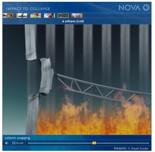
Yes, it's real, and sourced just like it looks: From PBS Nova, working directly with NIST to produce a "documentary" about why the Twin Towers "collapsed." Shyam Sunder was the director of NIST's WTC report if I recall correctly.
They really think lightweight sagging trusses could rip the columns away like that?
That is not even the weak point of the system.
What's even worse is people actually believe that really happened.
I think even "they" realized that this image, while trying to clearly illustrate NIST's hypothesis, only helps people realize how much nonsense it is.
Why do I say this? Because this image and others like it used to be all over the internet after this program came out. I had one hell of a time trying to find it again to post on ATS. But I uploaded it to my personal ATS media account now, so there will be no more hunting for it in the future. It appears to have been completely wiped from Google image searches though. I did lots of searches for "nist pbs nova" and etc. and was only able to eventually find it on a web forum where others were mocking it. Back when I ran the studyof911.com image library, this illustration was readily available and I hosted copies on that site. We had well over 2000 photographs and various illustrations, including photos of David Rockefeller sitting in on meetings with the WTC architects and engineers. A lot of the images I had uploaded back then seem impossible to find now.
This isn't even the original series of images I was looking for, which was even more ridiculous and showed a series of 3 separate images, but a screen shot of a video presentation that was hosted on the PBS website, as you can see.
edit on 27-4-2011 by bsbray11 because: (no reason
given)
reply to post by -PLB-
I would be very surprised if this was not entirely intentional. If they did mean "part" that would mean the vast majority of load would be carried in bending by the top chord. I can provide calculations proving the top chord would no way near have the capacity to withstand the required combined bending and tension forces, but it should be intuitive to most that if the rest of the truss has already failed in the system bending, the top chord (which was designed to carry compressive forces) is not going to be the hero to step up and take the bending force on its own which buckled and yielded the rest of the truss.
I (and I think most people) would interpret their sentence to mean that situation was progressively reached. They stated "progressively" just so people knew it wasn't suddenly. It seems you are trying to fit your partial catenary view to their words.
By the time maximum deflection is reached (after only 20 minutes) it is back to a parabola. Also, while it is a trapezium, it is at deflections which are less than the maximum. So no, it probably never goes much above 11.6, and if it does, it is not in that configuration when it is causing the columns to fail.
the word "most" should be "part". Although the question is how much this is really an error.
I would be very surprised if this was not entirely intentional. If they did mean "part" that would mean the vast majority of load would be carried in bending by the top chord. I can provide calculations proving the top chord would no way near have the capacity to withstand the required combined bending and tension forces, but it should be intuitive to most that if the rest of the truss has already failed in the system bending, the top chord (which was designed to carry compressive forces) is not going to be the hero to step up and take the bending force on its own which buckled and yielded the rest of the truss.
It doesn't state that this situation is actually reached, just that it progresses towards it
I (and I think most people) would interpret their sentence to mean that situation was progressively reached. They stated "progressively" just so people knew it wasn't suddenly. It seems you are trying to fit your partial catenary view to their words.
So the compressive diagonals in the middle fail as last. As result there isn't a parabola, but more of a trapezium shape, which has a different (larger) angle than your 11.6 degrees.
By the time maximum deflection is reached (after only 20 minutes) it is back to a parabola. Also, while it is a trapezium, it is at deflections which are less than the maximum. So no, it probably never goes much above 11.6, and if it does, it is not in that configuration when it is causing the columns to fail.
edit on 27-4-2011 by Azp420 because: (no reason given)
reply to post by exponent
I was being a bit nit-picky, but my school really drilled into us how to write these things properly. I would have liked them to summarize the results in the abstract. I also would have liked them to provide some calculations proving that the top chord has the capacity to withstand the claimed configuration and actions. I would have liked if the internal actions of the top chord were not kept hidden. A little bit of transparency, rather than just take our word for it.
My previous post(s) goes into the problem I have with this.
The example deflection you provided me with was exactly the same as the deflection claimed in the paper. 11.6 degrees still stands.
If you understand the calculation you will see this is working as intended. I am determining what the vertical component is of a load applied at a certain angle. If a truss is undergoing catenary action and it is perfectly flat, this means there is no vertical load.
Isn't that exactly the same as all simulation reports? What exactly do you expect them to do other than show you the input and output of their models?
I was being a bit nit-picky, but my school really drilled into us how to write these things properly. I would have liked them to summarize the results in the abstract. I also would have liked them to provide some calculations proving that the top chord has the capacity to withstand the claimed configuration and actions. I would have liked if the internal actions of the top chord were not kept hidden. A little bit of transparency, rather than just take our word for it.
I don't see how this is a problem with their model at all. Truss dynamics are pretty clear, once sufficient element breakages occur the upper chord will inevitably slip into tension.
My previous post(s) goes into the problem I have with this.
Furthermore your quote of 11.6 degrees is given from your calculation of a figure I gave on a previous page, not this paper at all.
It would be if 11.6 was referred to in the paper.
There was a lot more discussion after this point, but nobody seems to have noticed that 11.6 degrees is based on your calculations of my example of deflection, not of any actual scenario.
The example deflection you provided me with was exactly the same as the deflection claimed in the paper. 11.6 degrees still stands.
Furthermore, if you were to look at your calculation you would realise that it predicts 0 vertical load with a flat truss.
If you understand the calculation you will see this is working as intended. I am determining what the vertical component is of a load applied at a certain angle. If a truss is undergoing catenary action and it is perfectly flat, this means there is no vertical load.
I missed the whole NOVA doco for some reason.
I see where the OSers are getting this garbage from now, and why they can't explain what it is they're claiming.
Again I haven't seen the NOVA stuff, but I would take a guess they didn't actually explain how that is possible, and thus why the OSers can't either. Their whole argument is just an appeal to authority, it's a faulty generalization, a fallacy of defective induction. Nothing but a weak premise, only made legitimate because it comes from a source that people generally trust.
No OSer can make a legitimate argument of their own in defense of the OS, and I'll put a wager on that.
reply to post by ANOK
I haven't seen it but I am going to say it is wrong. Really? What is the matter with you. How about you go debunk it.
I haven't seen it but I am going to say it is wrong. Really? What is the matter with you. How about you go debunk it.
reply to post by esdad71
Have you seen the lolz screen grab from the doco bsbray11 posted? (Thanks for posting it by the way, it seems we all had a good laugh.)
I'll debunk it right here: Not possible.
The bolts would fail long, long, long before the column failed in double shear. If that's the kind of engineering used in the doco then the entire thing is no doubt full of bunk science.
edit on 27-4-2011 by Azp420 because: (no reason given)
Originally posted by esdad71
reply to post by ANOK
I haven't seen it but I am going to say it is wrong. Really? What is the matter with you. How about you go debunk it.
LOL, all I can do is repeat what has already been said.
If that is what you think happened there is no need to debunk anything. It debunks itself.
Seriously you really need to stop believing stuff just because it comes from an authority. What that screen shot is showing is simply ridiculous, and the fact that you require an explanation as to why it's ridiculous just shows your level of understanding.
It's nothing to do with opinion either, and don't ask me for proof, you first need to show your proof that what the pic shows is possible. Don't ask me to watch the doco, you should already know the answer I'm looking for if you know your own argument. Of course there is no proof, so I expect nothing from you other than some kind of deflection...
Originally posted by Azp420
the word "most" should be "part". Although the question is how much this is really an error.
I would be very surprised if this was not entirely intentional. If they did mean "part" that would mean the vast majority of load would be carried in bending by the top chord. I can provide calculations proving the top chord would no way near have the capacity to withstand the required combined bending and tension forces, but it should be intuitive to most that if the rest of the truss has already failed in the system bending, the top chord (which was designed to carry compressive forces) is not going to be the hero to step up and take the bending force on its own which buckled and yielded the rest of the truss.
As I pointed out earlier, the bending stress in the upper chord would be a lot less. The paper talks about failing compressive diagonals. There are different forces at play there. It doesn't seem intuitive to me that if a compressive diagonal fails, the upper chord also must fail. Seems to me only calculations or simulations can answer that.
I (and I think most people) would interpret their sentence to mean that situation was progressively reached. They stated "progressively" just so people knew it wasn't suddenly. It seems you are trying to fit your partial catenary view to their words.
By the time maximum deflection is reached (after only 20 minutes) it is back to a parabola. Also, while it is a trapezium, it is at deflections which are less than the maximum. So no, it probably never goes much above 11.6, and if it does, it is not in that configuration when it is causing the columns to fail.
Ok, but this is kind of speculative on your side, I would like to hear the authors about this before I jump to conclusions. Maybe it is an idea to send them an email with your criticism? I agree that the paper isn't very clear, but the wording they used doesn't really influence the result of their work, that horizontal force is still there.
The bolts would fail long, long, long before the column failed in double shear. If that's the kind of engineering used in the doco then the entire thing is no doubt full of bunk science.
Again, not intuitive to me. Can you show the calculations? Note that the claim is not that the pulling force made the columns snap but they buckled as result their loads. The pull force only put them a bit out of place, making the columns more susceptible to buckling.
edit on 27-4-2011 by
-PLB- because: (no reason given)
Originally posted by -PLB-
Note that the claim is not that the pulling force made the columns snap but they buckled as result their loads. The pull force only put them a bit out of place, making the columns more susceptible to buckling.
That is not so clear from their own literature:
NIST’s findings do not support the “pancake theory” of collapse, which is premised on a progressive failure of the floor systems in the WTC towers (the composite floor system—that connected the core columns and the perimeter columns—consisted of a grid of steel “trusses” integrated with a concrete slab; see diagram below). Instead, the NIST investigation showed conclusively that the failure of the inwardly bowed perimeter columns initiated collapse and that the occurrence of this inward bowing required the sagging floors to remain connected to the columns and pull the columns inwards. Thus, the floors did not fail progressively to cause a pancaking phenomenon.
wtc.nist.gov...
Remember that NIST worked directly with NOVA in creating what you see depicted above.
If it's not a pancake collapse, then what happens after the buckling hypothetically reaches some unspecified critical level?
reply to post by -PLB-
Your reasoning was full or errors and conclusion entirely incorrect.
Generally if a single element in a truss fails due to the truss being overloaded the entire truss will fail. If all the compressive diagonals have failed, as well as the bottom chord (leaving the tension diagonals with nothing to do), most people wouldn't give the top chord much hope to pick up that burden. I think the reason it is not intuitive to you is because the human brain is very good at filtering information and thought processes that contradict its beliefs.
If you would like to give accurate bending and tensile forces in the top chord which you think applied, and show how you got them, I will be able to give calculations describing if it has the capacity to withstand these.
For my first paragraph: If you want to call my interpretation of the report as it is written and assuming it means exactly what it says as speculation, so be it.
For my second paragraph: This is educated speculation with a low probability of being greatly different from what I described.
The paper seems clear enough to me, I know exactly what they are saying. But you're right, the wording really doesn't make a difference. I've shown that whether or not catenary action took the majority of the load, the model is bunk.
I was referring to the image posted on this page which shows the column failing in double shear rather than buckling.
reply to post by bsbray11
It waits around for upwards of 40 minutes (according to the model I've been bagging on), making sure there is complete symmetry around the perimeter of the tower, before giving the all-clear to the weight above to suddenly come down and fail the column, along with all the other perimeter columns. At the same time the internal columns, which are not bowed, decide they have had enough of this pesky fire, and decide to suddenly apply less upwards force to the weight above as it drops than they did five seconds before collapse.
As I'm still fairly new to looking at the collapse initiation I may have missed some important mechanisms, but that's how it's looking to me so far.
As I pointed out earlier, the bending stress in the upper chord would be a lot less.
Your reasoning was full or errors and conclusion entirely incorrect.
It doesn't seem intuitive to me that if a compressive diagonal fails, the upper chord also must fail. Seems to me only calculations or simulations can answer that.
Generally if a single element in a truss fails due to the truss being overloaded the entire truss will fail. If all the compressive diagonals have failed, as well as the bottom chord (leaving the tension diagonals with nothing to do), most people wouldn't give the top chord much hope to pick up that burden. I think the reason it is not intuitive to you is because the human brain is very good at filtering information and thought processes that contradict its beliefs.
If you would like to give accurate bending and tensile forces in the top chord which you think applied, and show how you got them, I will be able to give calculations describing if it has the capacity to withstand these.
Ok, but this is kind of speculative on your side
For my first paragraph: If you want to call my interpretation of the report as it is written and assuming it means exactly what it says as speculation, so be it.
For my second paragraph: This is educated speculation with a low probability of being greatly different from what I described.
I agree that the paper isn't very clear, but the wording they used doesn't really influence the result of their work, that horizontal force is still there.
The paper seems clear enough to me, I know exactly what they are saying. But you're right, the wording really doesn't make a difference. I've shown that whether or not catenary action took the majority of the load, the model is bunk.
Again, not intuitive to me. Can you show the calculations? Note that the claim is not that the pulling force made the columns snap but they buckled as result their loads. The pull force only put them a bit out of place, making the columns more susceptible to buckling.
I was referring to the image posted on this page which shows the column failing in double shear rather than buckling.
reply to post by bsbray11
If it's not a pancake collapse, then what happens after the buckling hypothetically reaches some unspecified critical level?
It waits around for upwards of 40 minutes (according to the model I've been bagging on), making sure there is complete symmetry around the perimeter of the tower, before giving the all-clear to the weight above to suddenly come down and fail the column, along with all the other perimeter columns. At the same time the internal columns, which are not bowed, decide they have had enough of this pesky fire, and decide to suddenly apply less upwards force to the weight above as it drops than they did five seconds before collapse.
As I'm still fairly new to looking at the collapse initiation I may have missed some important mechanisms, but that's how it's looking to me so far.
edit on 28-4-2011 by Azp420 because: (no reason given)
Originally posted by Azp420
Your reasoning was full or errors and conclusion entirely incorrect.
What exactly was wrong?
Generally if a single element in a truss fails due to the truss being overloaded the entire truss will fail. If all the compressive diagonals have failed, as well as the bottom chord (leaving the tension diagonals with nothing to do), most people wouldn't give the top chord much hope to pick up that burden. I think the reason it is not intuitive to you is because the human brain is very good at filtering information and thought processes that contradict its beliefs.
If you would like to give accurate bending and tensile forces in the top chord which you think applied, and show how you got them, I will be able to give calculations describing if it has the capacity to withstand these.
I always try to go by evidence or proof rather than intuition. I could give it a go, but I am not a structural engineer, it would take me quite some time. I can point out that bending stress would be less though. From my previous post:
Since the bending stress is linearly related to y, we know the bending stress is much lower in the lower part of upper chord.
But wouldn't it be quite a feat if you could prove NIST wrong and your intuition correct using your own model and calculations? It seems to me your are more experienced in this sort of thing than I am.
The paper seems clear enough to me, I know exactly what they are saying. But you're right, the wording really doesn't make a difference. I've shown that whether or not catenary action took the majority of the load, the model is bunk.
I have only seen you do calculation for a 100% catenary action. How is their model also bunk for partly catenary action?
reply to post by -PLB-
You cannot increase tensile forces in a member, increase bending forces in a member, and expect to have less internal stress in the member. It doesn't work like that. The added tensile forces are adding to the tensile stresses which are produced from the bending forces. This will cause the bottom of the member to tear open and fail.
May I ask what the evidence you are going by is in this case?
All bending stress is is an internal balance of tensile and compressive stresses within a member.
The neutral axis is where these compressive stresses meet tensile stresses and no stress exists. As you go lower in the upper chord the absolute value of y increases. The bottom of the upper chord is where you will find maximum stress.
It would be a feat, but I would liken it to someone making a climate change model which went against the UN status quo. Joe Public isn't knowledgeable enough to make an educated decision for himself so places his trust in the authority's model. NIST decided to keep their description limited to the highly technical collapse initiation. If they attempted to model the collapse itself every man and his dog would be pointing out the flaws in it.
I've described that in previous posts. It was proven bunk for any majority catenary action, and in the unlikely case of them completely misrepresenting their results, showed that it was highly unlikely the chord would not fail under the massive bending loads.
If I absolutely must provide numbers for proof though:
There would have been about a 322kNm moment (bending force) at the center of the chord. The chord was made up of two double angles 51 and 38mm deep. Double angles are used because it is a shape designed to resist axial loads. I'm not going to bother doing the calculations because I can tell you right now that a non-fire-damaged, 310UB46 (a 307mm deep beam with huge flanges at the top and bottom designed to take bending stresses) can only carry a 218kNm moment, and that's made from a higher grade of steel than was available when the towers were built!
I hope your intuition can see now that it will fail under a minority catenary action.
What exactly was wrong?
You cannot increase tensile forces in a member, increase bending forces in a member, and expect to have less internal stress in the member. It doesn't work like that. The added tensile forces are adding to the tensile stresses which are produced from the bending forces. This will cause the bottom of the member to tear open and fail.
I always try to go by evidence or proof rather than intuition. I could give it a go, but I am not a structural engineer, it would take me quite some time.
May I ask what the evidence you are going by is in this case?
I can point out that bending stress would be less though.
All bending stress is is an internal balance of tensile and compressive stresses within a member.
Since the bending stress is linearly related to y, we know the bending stress is much lower in the lower part of upper chord.
The neutral axis is where these compressive stresses meet tensile stresses and no stress exists. As you go lower in the upper chord the absolute value of y increases. The bottom of the upper chord is where you will find maximum stress.
But wouldn't it be quite a feat if you could prove NIST wrong and your intuition correct using your own model and calculations?
It would be a feat, but I would liken it to someone making a climate change model which went against the UN status quo. Joe Public isn't knowledgeable enough to make an educated decision for himself so places his trust in the authority's model. NIST decided to keep their description limited to the highly technical collapse initiation. If they attempted to model the collapse itself every man and his dog would be pointing out the flaws in it.
I have only seen you do calculation for a 100% catenary action. How is their model also bunk for partly catenary action?
I've described that in previous posts. It was proven bunk for any majority catenary action, and in the unlikely case of them completely misrepresenting their results, showed that it was highly unlikely the chord would not fail under the massive bending loads.
If I absolutely must provide numbers for proof though:
There would have been about a 322kNm moment (bending force) at the center of the chord. The chord was made up of two double angles 51 and 38mm deep. Double angles are used because it is a shape designed to resist axial loads. I'm not going to bother doing the calculations because I can tell you right now that a non-fire-damaged, 310UB46 (a 307mm deep beam with huge flanges at the top and bottom designed to take bending stresses) can only carry a 218kNm moment, and that's made from a higher grade of steel than was available when the towers were built!
I hope your intuition can see now that it will fail under a minority catenary action.
edit on 28-4-2011 by Azp420 because: (no reason given)
Originally posted by Azp420
You cannot increase tensile forces in a member, increase bending forces in a member, and expect to have less internal stress in the member. It doesn't work like that. The added tensile forces are adding to the tensile stresses which are produced from the bending forces. This will cause the bottom of the member to tear open and fail.
I don't really see how this relates to what I was saying:
situation 1: Upper and lower chord make up one rigid body (compressive diagonals have not failed).
situation 2: Upper chord progressively takes over the load (compressive diagonals fail).
In situation 1 the bending stress in the lower chord is much higher than the bending stress in the lower part of the upper chord of situation 2. I don't see how this line of reasoning is wrong.
May I ask what the evidence you are going by is in this case?
The evidence I know of are the models and tests by NIST and the one in the paper. I know of no evidence that shows the complete truss will fail when only one member of the truss fails.
The neutral axis is where these compressive stresses meet tensile stresses and no stress exists. As you go lower in the upper chord the absolute value of y increases. The bottom of the upper chord is where you will find maximum stress.
Yes. And ymax in a single chord is much smaller than ymax between two chords.
It would be a feat, but I would liken it to someone making a climate change model which went against the UN status quo. Joe Public isn't knowledgeable enough to make an educated decision for himself so places his trust in the authority's model. NIST decided to keep their description limited to the highly technical collapse initiation. If they attempted to model the collapse itself every man and his dog would be pointing out the flaws in it.
So what is keeping you? In my opinion this is the major problem with the truth movement as a whole. Assertions without proof, and anyone who does not agree has a distorted intuition and is influenced by confirmation bias. It is the standard mantra, even though you made a refreshing start.
I've described that in previous posts. It was proven bunk for any majority catenary action, and in the unlikely case of them completely misrepresenting their results, showed that it was highly unlikely the chord would not fail under the massive bending loads.
If I absolutely must provide numbers for proof though:
There would have been about a 322kNm moment (bending force) at the center of the chord. The chord was made up of two double angles 51 and 38mm deep. Double angles are used because it is a shape designed to resist axial loads. I'm not going to bother doing the calculations because I can tell you right now that a non-fire-damaged, 310UB46 (a 307mm deep beam with huge flanges at the top and bottom designed to take bending stresses) can only carry a 218kNm moment, and that's made from a higher grade of steel than was available when the towers were built!
I would really like to see which assumptions you make and how you get to those values. For example, do you assume that the upper chord carries all the load? It seems to me the 100% catenary is never reached. I don't think all compressive diagonals buckle, and I think they will keep at least some strength. This is illustrated in figure 8(b) where you see the diagonals progressively fail. Thats what I get from the paper. At one point, the truss itself fails (at 16.1 and 18 min). Isn't that the situation you are describing here, the moment the trusses will fail? And your point is that it should fail sooner? In that case, It would help to see your math.
I hope your intuition can see now that it will fail under a minority catenary action.
My intuition says that I should not base my opinion on my intuition .
reply to post by bsbray11
Here's a link to the original presentation:
www.pbs.org...
Just click the "Launch Interactive" next to the picture with the plane and building.
Edited to add:
We even get to hear Shyam Sunder explain what we're looking at:
"What then happened after the inward bowing, there was a stage at which the critical amount of inward bowing took place and the columns snapped and essentially the columns, once they snapped, the inwardly bowed columns suddenly sprung back and out."
Edited to add my own thoughts:
Doesn't this mean that the moment when "the columns snapped" is the real collapse initiation and shouldn't that be included in the NIST report?
edit on 28-4-2011 by NIcon because: (no reason given)
edit on 28-4-2011 by NIcon because: (no reason given)
Please forgive my brief reply once again, I have a conference call to prepare for
Well that's not too picky, but even so this is apparently a draft of the document. I'm too cheap to bother buying the journal it was published in / the full article to check it.
I'm not sure what actions you're talking about here, the top chord is specified as A50 steel (although I don't know if this is accurate, I seem to remember a lot of A36 in the trusses) and so we already have a good estimate for its UTS at about 500MPa. Perhaps you meant something else like the moment forces, this is down to just brevity I guess. Even so, I don't see why you think there needs to be any more transparency. This isn't a government report, it's a few people from a university. Call them up and ask them!
I've barely had a chance to read the thread so I might have missed it. I will go back and read it more thoroughly.
Forgive me but I read through the whole paper again and found absolutely no mention of 11.6 degrees, the nearest mention is 11.7 minutes until pull in forces developed. Perhaps you could quote it, or show me how you derived it. Solving a catenary for known deflection and arc length is a pain in the butt.
That isn't true, nor did you argue just for the vertical component of the load. You argued that because the angled truss did not apply its full self weight in vertical force, then the model was inaccurate. You cannot both argue this and then argue that a truss applying no weight whatsoever is accurate. Perhaps I missed part of your argument but this seems pretty contradictory to me.
I was being a bit nit-picky, but my school really drilled into us how to write these things properly. I would have liked them to summarize the results in the abstract.
Well that's not too picky, but even so this is apparently a draft of the document. I'm too cheap to bother buying the journal it was published in / the full article to check it.
I also would have liked them to provide some calculations proving that the top chord has the capacity to withstand the claimed configuration and actions. I would have liked if the internal actions of the top chord were not kept hidden. A little bit of transparency, rather than just take our word for it.
I'm not sure what actions you're talking about here, the top chord is specified as A50 steel (although I don't know if this is accurate, I seem to remember a lot of A36 in the trusses) and so we already have a good estimate for its UTS at about 500MPa. Perhaps you meant something else like the moment forces, this is down to just brevity I guess. Even so, I don't see why you think there needs to be any more transparency. This isn't a government report, it's a few people from a university. Call them up and ask them!
My previous post(s) goes into the problem I have with this.
I've barely had a chance to read the thread so I might have missed it. I will go back and read it more thoroughly.
The example deflection you provided me with was exactly the same as the deflection claimed in the paper. 11.6 degrees still stands.
Forgive me but I read through the whole paper again and found absolutely no mention of 11.6 degrees, the nearest mention is 11.7 minutes until pull in forces developed. Perhaps you could quote it, or show me how you derived it. Solving a catenary for known deflection and arc length is a pain in the butt.
If you understand the calculation you will see this is working as intended. I am determining what the vertical component is of a load applied at a certain angle. If a truss is undergoing catenary action and it is perfectly flat, this means there is no vertical load.
That isn't true, nor did you argue just for the vertical component of the load. You argued that because the angled truss did not apply its full self weight in vertical force, then the model was inaccurate. You cannot both argue this and then argue that a truss applying no weight whatsoever is accurate. Perhaps I missed part of your argument but this seems pretty contradictory to me.
Originally posted by NIcon
We even get to hear Shyam Sunder explain what we're looking at:
"What then happened after the inward bowing, there was a stage at which the critical amount of inward bowing took place and the columns snapped and essentially the columns, once they snapped, the inwardly bowed columns suddenly sprung back and out."
Thanks for the reminder. I haven't seen the actual video presentation in a while.
There you have it straight from the horse's mouth, that NIST's hypothesis, through all their convoluted and vague wording, is exactly how they presented it with NOVA above.
Again, this is their hypothesis:
new topics
-
Any one suspicious of fever promotions events, major investor Goldman Sachs card only.
The Gray Area: 1 hours ago -
God's Righteousness is Greater than Our Wrath
Religion, Faith, And Theology: 6 hours ago -
Electrical tricks for saving money
Education and Media: 9 hours ago -
VP's Secret Service agent brawls with other agents at Andrews
Mainstream News: 10 hours ago -
Sunak spinning the sickness figures
Other Current Events: 11 hours ago -
Nearly 70% Of Americans Want Talks To End War In Ukraine
Political Issues: 11 hours ago
top topics
-
VP's Secret Service agent brawls with other agents at Andrews
Mainstream News: 10 hours ago, 9 flags -
Cats Used as Live Bait to Train Ferocious Pitbulls in Illegal NYC Dogfighting
Social Issues and Civil Unrest: 14 hours ago, 8 flags -
Electrical tricks for saving money
Education and Media: 9 hours ago, 4 flags -
Nearly 70% Of Americans Want Talks To End War In Ukraine
Political Issues: 11 hours ago, 3 flags -
Sunak spinning the sickness figures
Other Current Events: 11 hours ago, 3 flags -
Late Night with the Devil - a really good unusual modern horror film.
Movies: 13 hours ago, 2 flags -
Any one suspicious of fever promotions events, major investor Goldman Sachs card only.
The Gray Area: 1 hours ago, 2 flags -
The Good News According to Jesus - Episode 1
Religion, Faith, And Theology: 16 hours ago, 1 flags -
God's Righteousness is Greater than Our Wrath
Religion, Faith, And Theology: 6 hours ago, 0 flags
active topics
-
Nearly 70% Of Americans Want Talks To End War In Ukraine
Political Issues • 20 • : FlyersFan -
-@TH3WH17ERABB17- -Q- ---TIME TO SHOW THE WORLD--- -Part- --44--
Dissecting Disinformation • 662 • : F2d5thCavv2 -
God's Righteousness is Greater than Our Wrath
Religion, Faith, And Theology • 12 • : randomuser2034 -
SETI chief says US has no evidence for alien technology. 'And we never have'
Aliens and UFOs • 61 • : andy06shake -
The Reality of the Laser
Military Projects • 47 • : F2d5thCavv2 -
Definitive 9.11 Pentagon EVIDENCE.
9/11 Conspiracies • 423 • : Lazy88 -
Election Year 2024 - Interesting Election-Related Tidbits as They Happen.
2024 Elections • 73 • : Threadbarer -
Sunak spinning the sickness figures
Other Current Events • 8 • : McUrnsalso -
HORRIBLE !! Russian Soldier Drinking Own Urine To Survive In Battle
World War Three • 36 • : TheMisguidedAngel -
British TV Presenter Refuses To Use Guest's Preferred Pronouns
Education and Media • 146 • : Consvoli