It looks like you're using an Ad Blocker.
Please white-list or disable AboveTopSecret.com in your ad-blocking tool.
Thank you.
Some features of ATS will be disabled while you continue to use an ad-blocker.

Free Energy Using Synthetic Tornadoes
page: 1share:
The following drawing and accompanying notes describe how to fabricate a synthetic tornado (ST). ST’s perpetually pump air without consuming
anything. The ST here pumps enough air to prove the feasibility of perpetual air flow. Better engineered ST’s will be able to pump enough air to
drive turbines to power a car, generate electricity, and so on. Hence free energy.
Notes.
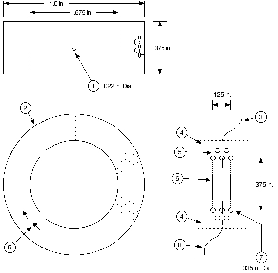
1. This ST consists of epoxy impregnated hollow core polyester thread wound around a spool. After the epoxy has cured, the spool is removed leaving behind the toroid (2). The toroid (2) is then given three coats of (gel type) copper bond epoxy in order to provide a good hard drill able surface. The thread has a part number of 361sy and is made by Invista. It is .002 in. in diameter and consists of 50 hollow core filaments.
2. The thread is purposely broken 6 evenly spaced times in the course of the wind. All the thread start ends (3 typical) and stop ends (8 typical) are positioned in the termination zone (6). The last 4 turns before a stop stay to the left of the termination zone and the last turn transition over to the zone with in the last quarter turn. The first 4 turns after a start stay to the right of the termination zone and the first turn transition over to the right with in the first quarter turn. The 7 start and 7 stop ends are relatively evenly distributed across the width of the termination zone.
3. The 5 output holes (5) and 5 input holes (7) are drilled in a staggered pattern so that any thread going into or out of the termination zone will be cut at least once. The air will be sucked into both ends of the input holes (7) and blown out of both ends of the output holes (5). For practical purposes, one end of the holes need to be plugged (but not filled) and the other connected to manifolds.
4. (1) is a typical PRC (pressure realization chamber) hole. The entire surface of the toroid outside the boundary lines (4) is to be covered with them. They are drilled in an 1/8 in. spacing hexagonal pattern with an angular offset of 1 in 2.89. This will result in every thread being cut at least once by a PRC hole approximately every .75 in. After drilling and cleaning out, these PRC holes are to be plugged but not filled on both ends. I used the same (gel type) copper bond epoxy for this.
5. The arrows (9) show the direction of air flow through the hollow filaments around the toroid. The air is propelled by the natural process called the channelized air effect (CAE). This Is the same natural process that creates the powerful air flow in tornadoes. This is why I call it a synthetic tornado. This internal perpetual air flow causes air to be sucked into holes (7) and blown out of holes (5).
Notes.
1. This ST consists of epoxy impregnated hollow core polyester thread wound around a spool. After the epoxy has cured, the spool is removed leaving behind the toroid (2). The toroid (2) is then given three coats of (gel type) copper bond epoxy in order to provide a good hard drill able surface. The thread has a part number of 361sy and is made by Invista. It is .002 in. in diameter and consists of 50 hollow core filaments.
2. The thread is purposely broken 6 evenly spaced times in the course of the wind. All the thread start ends (3 typical) and stop ends (8 typical) are positioned in the termination zone (6). The last 4 turns before a stop stay to the left of the termination zone and the last turn transition over to the zone with in the last quarter turn. The first 4 turns after a start stay to the right of the termination zone and the first turn transition over to the right with in the first quarter turn. The 7 start and 7 stop ends are relatively evenly distributed across the width of the termination zone.
3. The 5 output holes (5) and 5 input holes (7) are drilled in a staggered pattern so that any thread going into or out of the termination zone will be cut at least once. The air will be sucked into both ends of the input holes (7) and blown out of both ends of the output holes (5). For practical purposes, one end of the holes need to be plugged (but not filled) and the other connected to manifolds.
4. (1) is a typical PRC (pressure realization chamber) hole. The entire surface of the toroid outside the boundary lines (4) is to be covered with them. They are drilled in an 1/8 in. spacing hexagonal pattern with an angular offset of 1 in 2.89. This will result in every thread being cut at least once by a PRC hole approximately every .75 in. After drilling and cleaning out, these PRC holes are to be plugged but not filled on both ends. I used the same (gel type) copper bond epoxy for this.
5. The arrows (9) show the direction of air flow through the hollow filaments around the toroid. The air is propelled by the natural process called the channelized air effect (CAE). This Is the same natural process that creates the powerful air flow in tornadoes. This is why I call it a synthetic tornado. This internal perpetual air flow causes air to be sucked into holes (7) and blown out of holes (5).
so, you are saying that creating a vortex once is enough to keep it going indefinitely and extract energy from it?
is that correct?
is that correct?
Below is an excerpt from my paper “The Tornado And The Channelized Air Effect.” It is a technical explanation of CAE (Channelized Air Effect) and
should shed some light on how the ST (Synthetic Tornado) works.
Technical explanation
To explain what is going on lets start with the classic ideal gas model. Air consists of molecules, each of which move perpetually through space until it hit something as another molecule or a surface. At this time the molecule under goes a loss less collision and is redirected off into another direction. This process repeats it self over and over again for each molecule for ever.
For some people it sounds like gas molecules are violating some written law of physics. Obviously there not, but the feeling is a hint that just because a law is written down doesn’t mean that it is one hundred percent correct.
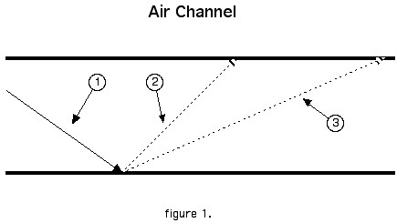
To continue lets look at figure 1. Arrow (1) shows the path of a molecule before it hits the surface of an air channel. If the surface was perfectly smooth then the molecule would bounce off at an angle equal to the angle of incident. However the surface will never be perfectly smooth at the molecular level so the molecule could bounce off at a typically steeper angle as in arrow (2) or at a typically swallower angle as in arrow (3). A molecules traveling along (2) will under go another random path correcting collision before one traveling along (3). It is not necessary that molecule travels from one side to another without a colliding with another molecule. If it does collide then it will, on the average, transfer its directional bias to the other molecule. This conditional frequency of wall collisions translates to the rule that the more a molecule is traveling along the length of the channel the fewer path correcting wall collisions it under goes. This rule results in an average directional bias along the length of the channel for the molecules in the channel. This directional bias is airflow.
Figure 1 shows the air flowing from left to right. The CAE process could easily result in a right to left flow. The direction that wins out is the result of a tug or war involving the whole system. The direction that results in the largest number of molecules being channelized has the greater push and will win out. For the hair comb case, air flow coming in through sides and being force to exit through the small bottle neck teeth ends results in the greatest number of molecules being bunched up and channelized between the teeth. Thus we observe air coming from the ends and not going into them.
It is easy to rationalize that, on the average, each molecule wall collision results in a very small increase in air velocity. Thus the change in velocity is directly proportional to the total number of wall collision. This is directly proportional to the total channel surface area and inversely proportional to the air velocity. The total ram force is proportional to the air velocity squared. This means that the change in force is proportional to the produce of the velocity and the change in velocity. The final result here is that the total increase in ram force is directly proportional to the total channel surface area and independent of air velocity. It will be seen later how this independents is the key to producing real power from CAE.
Technical explanation
To explain what is going on lets start with the classic ideal gas model. Air consists of molecules, each of which move perpetually through space until it hit something as another molecule or a surface. At this time the molecule under goes a loss less collision and is redirected off into another direction. This process repeats it self over and over again for each molecule for ever.
For some people it sounds like gas molecules are violating some written law of physics. Obviously there not, but the feeling is a hint that just because a law is written down doesn’t mean that it is one hundred percent correct.
To continue lets look at figure 1. Arrow (1) shows the path of a molecule before it hits the surface of an air channel. If the surface was perfectly smooth then the molecule would bounce off at an angle equal to the angle of incident. However the surface will never be perfectly smooth at the molecular level so the molecule could bounce off at a typically steeper angle as in arrow (2) or at a typically swallower angle as in arrow (3). A molecules traveling along (2) will under go another random path correcting collision before one traveling along (3). It is not necessary that molecule travels from one side to another without a colliding with another molecule. If it does collide then it will, on the average, transfer its directional bias to the other molecule. This conditional frequency of wall collisions translates to the rule that the more a molecule is traveling along the length of the channel the fewer path correcting wall collisions it under goes. This rule results in an average directional bias along the length of the channel for the molecules in the channel. This directional bias is airflow.
Figure 1 shows the air flowing from left to right. The CAE process could easily result in a right to left flow. The direction that wins out is the result of a tug or war involving the whole system. The direction that results in the largest number of molecules being channelized has the greater push and will win out. For the hair comb case, air flow coming in through sides and being force to exit through the small bottle neck teeth ends results in the greatest number of molecules being bunched up and channelized between the teeth. Thus we observe air coming from the ends and not going into them.
It is easy to rationalize that, on the average, each molecule wall collision results in a very small increase in air velocity. Thus the change in velocity is directly proportional to the total number of wall collision. This is directly proportional to the total channel surface area and inversely proportional to the air velocity. The total ram force is proportional to the air velocity squared. This means that the change in force is proportional to the produce of the velocity and the change in velocity. The final result here is that the total increase in ram force is directly proportional to the total channel surface area and independent of air velocity. It will be seen later how this independents is the key to producing real power from CAE.
How expensive would this be to research further and also to fund? Would it be worth it, how about opportunity cost?
it's easy to rationalize that overall airspeed would increase if and only if impacting molecules only came one way.
molecular motion vectors would be randomly distributed, 'windspeed' , being extremely slow compared to individual molceluar motion, plays in a different league altogether.
i'm not saying that it can't have an effect, but to have one, you'd have to de-randomize molecular velocity vectors, by reflecting in a preferred direction. even then, how far do you think does a gas molecule tavel before it hits another? i surface area comes into play, the pipes would have to be extremely thin to get decent results, if i'm not mistaken. if you were able to affect volume, however... i don't know, though, from what you've said, only the surfaces are important, right?
As for how much it would cost to do further research, the answer is this, I am still able to design and fabricate improved version of ST’s on my
current budget which is zero.
As for the question that I think you are implying, “How much am I trying to collect ?”. This answer is this. Because of the prolific free energy frauds, there are two golden rules which I new I had to follow.
1. Do not withhold technical information.
2. Never mention money.
As for Long Lance’s question, I really do appreciate you taking an interest in ST’s and especially taking the time to reply. I think the answer to your question can to found if you carefully ponder what I have written. Writing is not my specialty and this is the best I can do.
Can I pay you to make me one of these that will power whatever you want to hook it up to to provide energy?
What I mean by this is, is there any appliance, no matter how big or small, that this technique can power, and can you create it?
For instance, the pump that powers the filter cycle for my aquarium uses energy from the grid. Can you rig this pump to use this technique for free energy?
I will put it this way, I dont know jack about science, I am just an interested consumer. If I can buy something that will power some of my appliances and help me significantly cut the utility bill, I will.
DO YOU HAVE THIS PRODUCT AND WILL YOU SELL IT TO YOUR AVERAGE CONSUMER!?
At best, the ST documented here could be marketed as a very weak silent fan which never stops blowing air. Even then it is debatable whether it is
more novel than practical.
I posted this ST to encourage multiple independent minds (hopefully with larger budgets) to do their own reachers. This open competition is the quickest way bring practical energy producing produce to market. Products which I myself can not wait to acquirer.
I am not setup for any kind of production. However, Their is enough information here for a third party to mass produce and market this ST. I am in no position to say no.
Certainly you have a proof of concept prototype which has validated your engineering. Youtube is free to register and post video...
Let's see!
Let's see!
So, if somebody could give you whatever you needed, how much do you think it would cost to make one of these that can power my aquairum pump?
This is what I am using right now
Would it be more or less in the 100$+ range?
Cuz this ting uses 96 watts and runs 24/7, probably will be doing so for several years. I sure could use something to save money on that.
[edit on 5/30/2007 by DYepes]
Would it be more or less in the 100$+ range?
Cuz this ting uses 96 watts and runs 24/7, probably will be doing so for several years. I sure could use something to save money on that.
[edit on 5/30/2007 by DYepes]
The issue is not if an ST can be built to provide enough pressure for an aquarium air pump. The issue is the unknown path to get there. Up scaling
the design here would be impractical. I need to come up with a design which produces more pressure. I am working on a what I think will be a better
design now. I will not know how much better or even If until after I have finished and tested it. On top of that I don’t know how many
generations I will have to go through before I feel there is enough pressure until I have built and tested each generation.
Once I have enough pressure, the cost to upscale and produce can be done by some one familiar with estimating manufacturing costs.
I wish I was being paid to do this research. But, I am not going to stop research and wait to be paid.
If I were to take an intuitive guess base on my work with ST’s, I would say a mass produced aquarium air pump would be about the size of the ST documented here and would cost less than $10 each. After all it would be just a piece of plastic.
I see... how much money would you need to have this pump ready by the end of this year? See I am not an enginner, but I do have a modest amount of
money.
Do you think 1500$ would be enough to have one of these air pumps by the end of this year that is equivelant to the one I have now?
Do you think 1500$ would be enough to have one of these air pumps by the end of this year that is equivelant to the one I have now?
I have just finished fabricating and evaluating my latest ST design. I am happy to report that it does have significantly improved performance
relative to the one documented here. I am starting on a, hopefully, better design.
There are two exercises I would like to see done.
1. Up scaling: I would like to see ST’s made using the latest design which are are between 10 and 100 times larger in volume. This will help answer the question of whether the performance relative to volume is linear, quadratic, or something else.
2. Channel size: The current material I am using (361SY) has one hole per filament. Increasing the number of holes per filament would decrease the channel size improving the performance. The question to be answered here is, What is the performance relative number of holes per filament.
Decreasing channel size to improve performance dose not change the over all size of an ST design. The limit in channel size is the size of an air molecule. We are a very long ways from there. Hence, We are a very long ways from the maximum performance per unit volume.
The results of these two exercise along with the latest ST design will allow one to estimate the size and production cost of practical energy producing ST’s.
what do you mean by 'filaments' if it's wound in a coil pattern, does it even matter how many threads you use?? could you post photos of parts or
the whole assembly, in action if at all possible?
As mentioned in the notes the thread consists of 50 filaments and each filament is hollow. The thread was originally developed by Dupont for the
purpose of making fabric with a trade mark name of Thermostat. The hollow cores was intended to increase its insulating ability. This product line
was later sold to Invista.
The number of threads does make a difference. One long thread is better than many short ones. Because, one long channelizing channel is better then many short ones. Although the filaments are broken at each hole, one must remember that the filaments were stretched out and frozen in place with epoxy before breaks where placed in them. This results in the ends on opposite sides of the hole being nearly perfectly lined up so that air coming out of one end and going into the other will jump the gap with minimal loss or bunching. It turns out that some bunching is a good thing. After each gap the air has been slightly compressed and is a little denser. The next section of channelizing will organize the air reducing the pressure but not the density. This processes is repeated thousands of times. This is why I call the holes PRC holes for pressure realization chambers.
When the air finely gets to the end of a filament it doesn’t just all spill out of the very end. The back pressure ripples back through the PRC’s causing a little air to leave the filament at each PRC hole as it approaches the end. This air drifts down the holes until it is absorbed by filaments that are just starting. I will stop here and let you ponder what you just read.
Just about all frauds relay on some sort of doctored visual (video/still picture) evidence. The situation is so bad, that it is my opinion that posting a picture as evidence will do more harm than good. The same goes for eyewitness endorsements. There are eye witnesses to working ST’s, including a professor in the engineering department at a university and a staff member of abovetopsecret.com. (which is how I learned about ATS in the first place.) As this thread was getting start I requested these eye witnesses to remain silent.
If you still want something physical to sink your teeth into, consider this. The world’s largest perpetual motion machine has been hiding above are heads for billions of years. Its the Jet Stream. A small extension to the technical description of CAE given here can explain the perpetual air flow. It can also explain why the air travels in direction of the earths rotation.
So you're saying the air molecule will go faster every time it hits a wall?
I don't understand where the energy is coming from. The air isn't going to blow around indefinitely inside the device. As far as I can see, there
is no physical mechanism that will keep the device going. I also cannot find any online information on the channelized air effect; the only things I
get in google that contain that phrase are some of your other ATS posts. Are you able to let us see the journal paper you mentioned? It looks like
whatever you expect to power this device has something to do with the CAE, and I can find no information on it.
Is something like this what you are referring to?
Solar Tower
Link 2
Link 3
[edit on 22-9-2007 by MBF]
Solar Tower
Link 2
Link 3
[edit on 22-9-2007 by MBF]
For those of you who are new to this thread, your best bet to understand what is going on is to carefully ponder my CAE technical description post
above.
In reference to not being able to find any other information on CAE, It is possible for some one to have an original Idea.
I could not get my paper published. As soon as you even hint at free energy publishers automatically say NO. ATS, however, doesn't care.
Synthetic Tornadoes are in no way related to Solar Towers.
You do realize that technology very similar to this was perfected by Victor Schauberger? After an initial start he created wind vortexes that
provided both power and lift. He was forced to create some devices to be used by Nazi Germany. An underhanded American company got him to sign his
rights away to his invention.
www.newphys.se...
www.newphys.se...
new topics
-
Late Night with the Devil - a really good unusual modern horror film.
Movies: 1 hours ago -
Cats Used as Live Bait to Train Ferocious Pitbulls in Illegal NYC Dogfighting
Social Issues and Civil Unrest: 2 hours ago -
The Good News According to Jesus - Episode 1
Religion, Faith, And Theology: 4 hours ago -
HORRIBLE !! Russian Soldier Drinking Own Urine To Survive In Battle
World War Three: 6 hours ago -
Bobiverse
Fantasy & Science Fiction: 9 hours ago -
Florida man's trip overseas ends in shock over $143,000 T-Mobile phone bill
Social Issues and Civil Unrest: 9 hours ago -
Former Labour minister Frank Field dies aged 81
People: 11 hours ago
top topics
-
Florida man's trip overseas ends in shock over $143,000 T-Mobile phone bill
Social Issues and Civil Unrest: 9 hours ago, 8 flags -
SETI chief says US has no evidence for alien technology. 'And we never have'
Aliens and UFOs: 13 hours ago, 7 flags -
Cats Used as Live Bait to Train Ferocious Pitbulls in Illegal NYC Dogfighting
Social Issues and Civil Unrest: 2 hours ago, 7 flags -
This is our Story
General Entertainment: 16 hours ago, 4 flags -
Former Labour minister Frank Field dies aged 81
People: 11 hours ago, 4 flags -
Bobiverse
Fantasy & Science Fiction: 9 hours ago, 3 flags -
HORRIBLE !! Russian Soldier Drinking Own Urine To Survive In Battle
World War Three: 6 hours ago, 2 flags -
Late Night with the Devil - a really good unusual modern horror film.
Movies: 1 hours ago, 2 flags -
The Good News According to Jesus - Episode 1
Religion, Faith, And Theology: 4 hours ago, 0 flags
active topics
-
President BIDEN Vows to Make Americans Pay More Federal Taxes in 2025 - Political Suicide.
2024 Elections • 96 • : CriticalStinker -
Cats Used as Live Bait to Train Ferocious Pitbulls in Illegal NYC Dogfighting
Social Issues and Civil Unrest • 8 • : lordcomac -
British TV Presenter Refuses To Use Guest's Preferred Pronouns
Education and Media • 140 • : Annee -
Florida man's trip overseas ends in shock over $143,000 T-Mobile phone bill
Social Issues and Civil Unrest • 16 • : grey580 -
HORRIBLE !! Russian Soldier Drinking Own Urine To Survive In Battle
World War Three • 22 • : RickyD -
SETI chief says US has no evidence for alien technology. 'And we never have'
Aliens and UFOs • 35 • : Consvoli -
Late Night with the Devil - a really good unusual modern horror film.
Movies • 1 • : DAVID64 -
Ditching physical money
History • 18 • : annonentity -
Lawsuit Seeks to ‘Ban the Jab’ in Florida
Diseases and Pandemics • 32 • : SchrodingersRat -
"We're All Hamas" Heard at Columbia University Protests
Social Issues and Civil Unrest • 279 • : KrustyKrab