It looks like you're using an Ad Blocker.
Please white-list or disable AboveTopSecret.com in your ad-blocking tool.
Thank you.
Some features of ATS will be disabled while you continue to use an ad-blocker.

Tube drills at GP were not done by ancient Egyptians.
page: 4share:
The AE's made a bed frame out of copper tubing, so we can't pretend they couldn't make copper tubes. Somehow you seem to think I haven't really investigated this sawing procedure and the tools required. You shouldn't make such an assumption.
Good. Then you can tell me how they joined the seam of the tube. Brazed together? Requires a continuous jet of flame. Could they do that? Soldered? Let’s not go there. Cast? They did have rather a lot of sand .
You’re forgetting that as a machinist , I too have been fascinated by these cores. You’ll notice too that I never inferred the AE couldn’t make copper tubes I’m interested in how they made them for a start .
Referring back to the AE cores, I’ve mentioned that the average thickness of these tube drills was 1mm at the base of the cut.
We’ve all seen the pics some are very impressive , there’s a particular one where the entire hole has been split in half , looks like a good 10” drill did it .
Obvious 1mm blade cut at the bottom of the hole.
You’re telling me Stocks never knew this?
Just so everyone else can get their heads round it,a
Quick tooling lesson. A cutting tool wants to work with the least resistance it can encounter. In this case, a 1mm blade thickness is ideal for this type of procedure- a ‘plunge’ cut- only 1mm of tool ‘face’ is cutting offering the minimal resistance they could achieve .
Stocks used an easily 8mm thick flat bottomed extruded (stronger) tube. It’s no bloody wonder it took him so long with 8mm of tool resistance at the face of the cut . It wouldn’t ‘cut’ like a thin blade .
This leads me to apply the logic that the AE were ‘cutting’ and that was their intention.
It also leads me to apply it in the sense that Stocks was only interested in abrasion .
Whether Stocks deliberately chose a thick pipe to prevent tool failure using his technique is up for debate . I would say he did if you know anything about tooling. And AE tooling.
He also removed the core by banging it out with a STEEL chisel. The AE didn’t have steel for this job just copper. Why didn’t he use copper like they ‘did’? Because it would bend.
Now with a 1mm gap around your core, it’s a far easier gap to ‘wedge’ and break the core out. Could even use granite as a wedge and bust it out.
As for core 7 and the incisions left upon it, as a machinist you’ll have a hard time convincing me that these helical continuous cuts that give a calculable feed rate are anything other than what they purport to be. Tooling striations left by a sharp edge.
For what it’s worth , I always thought the marks on core 7 were left toward the end of the procedure as they are quite high up the core. You often get striations made by the entire tool when you have reached your cut depth, therefore you’ll always have some at the top , even if the entire hole has been gradually ‘reamed’ out by the tool during the length of the procedure. That is what I think they are. The last turns of the tool , leaving marks higher up the core.
a reply to: Harte
edit on 22-9-2020 by bluesfreak because: (no reason given)
edit on 22-9-2020 by bluesfreak because:
Spelling!!
edit on 22-9-2020 by bluesfreak because: (no reason given)
edit on 22-9-2020 by bluesfreak because: (no
reason given)
a reply to: bluesfreak
Rolled I presume.
Pics of some of the fittings here (page 12.)
More about the bed here.
From Reisner.
Articles from Reisner are available online in pdf format. They are quite long. But I'm not really surprised you didn't know about this, since you are too busy denying the possibility. If you ever took the time to investigate your own claims, you might find Reisner's description and some better pics. This sufficed for me when I was looking into whether any copper tubes had ever been found. They have, but not drills (AFAIK,) though Reisner does list a "model drill" found at Giza, I don't know if it was a copper tube drill - could have been for wood for all I know.
Lastly, I'd point out that there need not be any tight seam at all on a tube drill. It will work without one, it just needs to have enough thickness to hold the shape.
Harte
edit on 9/23/2020 by Harte because: of the wonderful things he does!
Rolled I presume. Pics of some of the fittings here (page 12.) More about the bed here. From Reisner. Articles from Reisner are available online in pdf format. They are quite long. But I'm not really surprised you didn't know about this, since you are too busy denying the possibility. If you ever took the time to investigate your own claims, you might find Reisner's description and some better pics. This sufficed for me when I was looking into whether any copper tubes had ever been found. They have, but not drills (AFAIK,) though Reisner does list a "model drill" found at Giza, I don't know if it was a copper tube drill - could have been for wood for all I know. Lastly, I'd point out that there need not be any tight seam at all on a tube drill. It will work without one, it just needs to have enough thickness to hold the shape. Harte
Well it’s a funny old world , claim and counter claim forever.
And yes !! Guess what?! I have read much by Reisner, but not all of it ‘sufficed’ for me.
So. ‘Rolled’ , you presume . Around what ? You need a decent accurate wooden cylinder to bend your sheet around . No way of creating those according to you , because they didn’t have lathes, did they, to make one. According to your beliefs .
One has to make a more than reasonably accurate circle to work as a drill.
And while we’re at it let’s get some terminology straight . When I say ‘drill’ I mean ‘tube drill’ NOT some massive solid drill bit. Today we would call this type of tool a ’holesaw’. But we can call it ‘drilling ‘ and that’s ok .
Secondly , I do believe they used abrasive to aid cutting , just not sand as Stocks claims . Corundum, for sure , but also every semi precious stone we know them for Lapis, Turquoise, for example are harder than granite .
Regarding core 7 ,Reisner is another one who likes to dismiss things out of hand . He states that ‘of course’ the core shows no continuous helical striations and the ‘untrained ‘ eye gets mistaken by striations that ‘cross’ each other.
Well first of all, all drilling procedures require slight removal of the drill every now and then to remove swarf and material , you just HAVE to. To save your tool and to remove waste. So you WOULD get crossover striations as you turn the tool again to restart the procedure.
Bit of Sleight of hand there by Reisner I feel.
I disagree with Reisner that they started with a blunt tool which became sharpened by the action . I see how a tool tip would change under a ‘slow grind’ but not so at a faster rate .
I think a tool with a pre sharpened edge would retain its edge shape and self sharpen according to the resultant shape it was cutting . To start the procedure you would want something sharp so I disagree with him there.
It also depends on the speed of rotation of the tool, which I believe is faster than you think.
This led me to a thorough investigation of Dunn’s claims.
He’s hardly an ‘untrained ‘ eye, and if you can’t give him his dues for the level he’s worked at in the aerospace industry - those guys are top of the game - then you have a problem I’m afraid .
I wonder, have you ACTUALLY read Dunn’s book regarding tooling and the section on core 7?
The thing that surprised me about Dunn was something I had not expected after the way people like you talk about him on here; there are many times he tries to ‘disprove’ his own theory , he is way more balanced than people like you would have others believe.
In Dunn’s book he proves a helical cut exists , continuously with a verifiable rate.
He Also proves that previous pictures in an academic investigation of the core were disingenuously tilted so the striations appear horizontal, when in fact they are not.
I’m open to the possibility they may have used other techniques , may have used jewelled tooling , may have poured abrasive in to the edges of the cut, or down the tube or both .
My argument is that Stocks is unreliable .
I also think they could rotate them faster than you think.
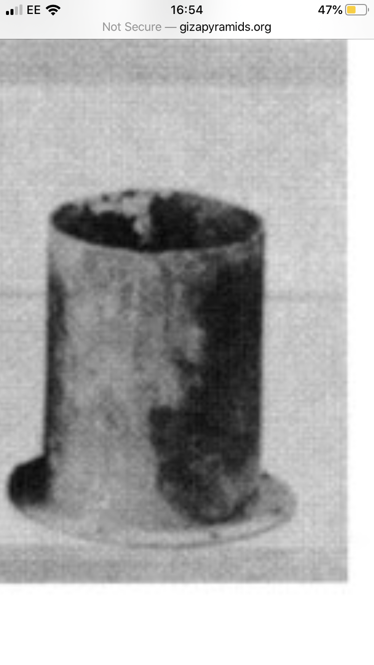
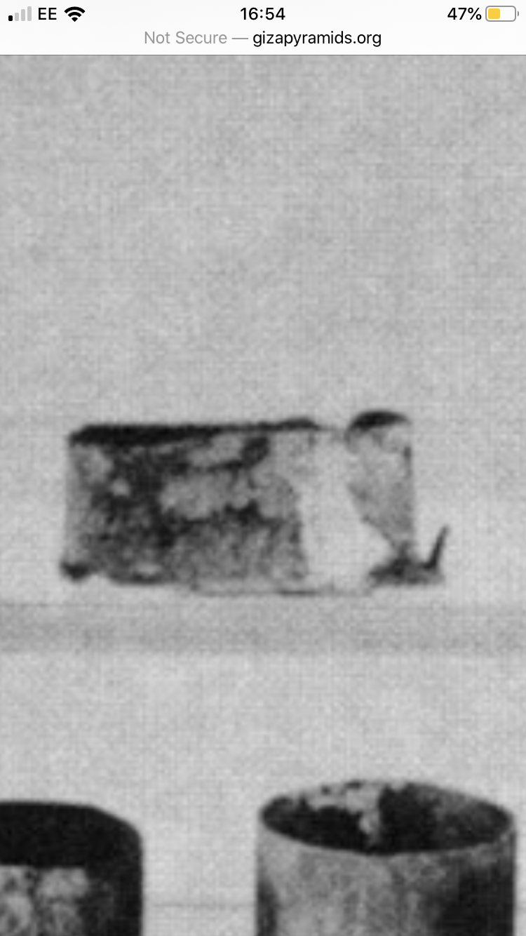
These AE tube drills do show an impressive level of fabrication .
They have holes drilled in the base at regular intervals , for fixing I presume (the other shows some form of spiked attachments . They are solid not with a gap down the seam and have a sharpened blade end . Yes, could be worn that way too . Seems like the AE are attaching them differently to a shaft than those who have tried to replicate it. Why?
How DID they join that seam eh?
a reply to: Harte
edit on 23-9-2020 by bluesfreak because: (no reason given)
edit on 23-9-2020 by bluesfreak because: (no reason
given)
edit on 23-9-2020 by bluesfreak because: (no reason given)
a reply to: bluesfreak
Not taking the time to check, but those pics of yours look like the copper fittings for the bed I mentioned. The fittings Reisner published photos of. They aren't drills, just evidence that the AE's made copper tubes.
To the rest, we know they used bow drills on wood from their artwork. We know they used bow drills to make beads - again, from their artwork. We know they used bow drills in lapidary shops - they've been found (not the bow, but the drill shaft and bit.) We know they made copper tubing, from this bed. We know that a copper tube drill will drill holes in granite using an abrasive. I don't see the sticking point, nor why Stocks is unreliable. The man just demonstrated how it could have been done with a bow drill and a copper tube. I've seen people on youtube drill granite by hand using a bit with an offset handle that you spin manually by moving your arm back and forth. Can't remember what it's called, but these are also shown in Egyptian artwork.
Not seeing the argument.
Harte
So they sharpened the end of their bed frame tubes did they? To resemble post cut tube drills? Seems like a waste of time .
Could you also show me where I said they couldn’t make copper tubes , as I can’t find it, but you seem to think that’s the main point to silence me??
Harte just loves to keep a thread alive by asking YOU questions without having the decency to address any points YOU raise . Every bloody time.
So utterly boring . snore.
explain why the mentioned striations on core 7 are continuous , and travel down the core in a helical manner and at a calculable stable feed rate .
You didn’t answer whether you had actually read Dunn’s work.
You don’t see any sticking point except you like to hold Stocks up as an example to others on here when the reality is he messed up big time, very sloppy work.
My position is yes, all of the above methods work, yet, the rotational speed doesn’t match the forensics found on core 7.
Perhaps you can explain that in relation to the engineering principles I have outlined previously .
I think they were rotating them a lot faster that we give them credit for.
A higher speed of the cutter allows lighter , faster cutting, and not near the amount of wear on a tool.
If they were spinning a tube drill at say 800rpm -easily achievable by hand cranking and maybe the aid of a fly wheel- then with abrasives combined I’m pretty sure you could cut into granite at the feed rate seen by Petrie and indeed Dunn.
Perhaps you could clarify which part of Dunn’s methodology is wrong in his work regarding core 7?
Perhaps you could also explain why an Academic article on the core was found to be ‘not entirely truthful’ in the way they presented pictures of the core, tilting it to make the striations appear horizontal when they are not. What purpose did that serve other than to make a picture fit your argument?
What good did that do for our understanding of AE tooling ?
What purpose does it serve having Dunn prove that the tooling marks are helical?
It means the ‘cutting’ of the core proceeded in a faster manner than people like you, Stocks and Reisner would have us believe .
As a machinist I’m always very interested in how jobs are set up to achieve the required result .
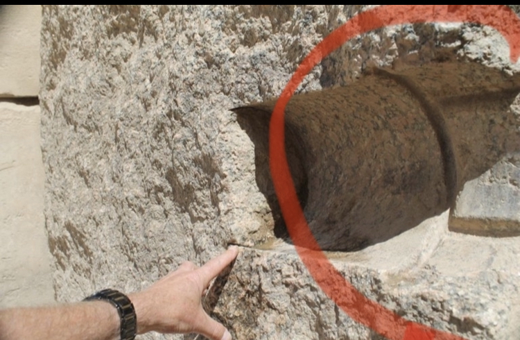
The right hand side of this picture that I ringed is actually more interesting to me than the hole itself.
There’s a lot of ‘setting up work’ done here. These grooves I imagine held some sort of a jig for stability of the tool, to ensure there is no ‘tool drift’ but mainly for rigidity.
This doesn’t look like they simply stood above this hole and slowly ground it out, does it? It looks like quite a sophisticated set up to hold it rigid enough to make a hole of this size. Why would you need rigidity?
A higher tool speed.
I’m Harte
Could you also show me where I said they couldn’t make copper tubes , as I can’t find it, but you seem to think that’s the main point to silence me??
Harte just loves to keep a thread alive by asking YOU questions without having the decency to address any points YOU raise . Every bloody time.
So utterly boring . snore.
explain why the mentioned striations on core 7 are continuous , and travel down the core in a helical manner and at a calculable stable feed rate .
You didn’t answer whether you had actually read Dunn’s work.
You don’t see any sticking point except you like to hold Stocks up as an example to others on here when the reality is he messed up big time, very sloppy work.
My position is yes, all of the above methods work, yet, the rotational speed doesn’t match the forensics found on core 7.
Perhaps you can explain that in relation to the engineering principles I have outlined previously .
I think they were rotating them a lot faster that we give them credit for.
A higher speed of the cutter allows lighter , faster cutting, and not near the amount of wear on a tool.
If they were spinning a tube drill at say 800rpm -easily achievable by hand cranking and maybe the aid of a fly wheel- then with abrasives combined I’m pretty sure you could cut into granite at the feed rate seen by Petrie and indeed Dunn.
Perhaps you could clarify which part of Dunn’s methodology is wrong in his work regarding core 7?
Perhaps you could also explain why an Academic article on the core was found to be ‘not entirely truthful’ in the way they presented pictures of the core, tilting it to make the striations appear horizontal when they are not. What purpose did that serve other than to make a picture fit your argument?
What good did that do for our understanding of AE tooling ?
What purpose does it serve having Dunn prove that the tooling marks are helical?
It means the ‘cutting’ of the core proceeded in a faster manner than people like you, Stocks and Reisner would have us believe .
As a machinist I’m always very interested in how jobs are set up to achieve the required result .
The right hand side of this picture that I ringed is actually more interesting to me than the hole itself.
There’s a lot of ‘setting up work’ done here. These grooves I imagine held some sort of a jig for stability of the tool, to ensure there is no ‘tool drift’ but mainly for rigidity.
This doesn’t look like they simply stood above this hole and slowly ground it out, does it? It looks like quite a sophisticated set up to hold it rigid enough to make a hole of this size. Why would you need rigidity?
A higher tool speed.
I’m Harte
edit on 24-9-2020 by bluesfreak because: (no reason given)
originally posted by: dragonridr
a reply to: Harte
Here is some russians showing you how egyptians cut through stone with a core drill.
Oh and pay attention near the end where they talk about the cores they get and why they match up to petries discription.
That's the offset handle I was talking about. There are several examples of its use on youtube.
Harte
Ha ha! Now Harte using the very Medium he hates others to use - ‘independent researchers on YouTube’ to make his point . Priceless. Just
Priceless.
All the cotton windings those guys do in their cores are a showing a feed rate WAY faster than the 0.1000” of an inch shown on the Petrie core. Those cotton wraps following a ‘spiral’ those guys are doing are like 5mm per revolution .?!
One is even perhaps 15mm per revolution which is insane even by the crystal powered drill brigade standards .
That would be an incredible granite feed rate beyond today’s capabilities for sure.
So they aren’t proving much there relating to the original claim per revolution.
Abrasive additives are surely going to cause confusion and noise on a surface so definitives are always going to be a problem , goes without saying.
Petrie identified a consistent pitch to a tool between striations. He probably carried a set of pitch keys being an engineer and used them to identify one .
What you fail to address is the possibility that either method can produce the same results .
A sharpened core drill with the blade angled in ,turned faster, would produce the same results .
It would also take less time as the harder than granite abrasive is also flying round inside quicker doing more damage more efficiently .
Discounting faster tool speeds as a reason for some of the forensics is lazy engineering.
Everyone’s got a point to prove , a book to sell (including academia) a video to make , subscribers to gain , followers to nourish.
The fact that you have settled back into your chair with what you are satisfied is the definitive answer with no need to consider other reasons for the forensics is all I need to know here.
No one in that video talks about faster tool revolutions being another possible answer for the forensics .
Do You think something as human and enquiring As this conversation never happened in AE between master stone workers ? :
AT THE HARTOTEP STONE WORKSHOP
#1 “ surely we can do this better if we can spin it a bit faster ?”
#Hartotep “ erm..”
a reply to: Harte
originally posted by: bluesfreak
Can you explain what type of tool you think they used? How it worked, how it was made and by whom?
edit on 24/9/20 by Hanslune because: (no
reason given)
originally posted by: bluesfreak
I think it’s the same tool type , (could be some slight modifications ) the same people , only turned faster held more rigid .
It’s where people with an engineering mind would arrive at after a while .
a reply to: Hanslune
Thanks
So it was the ancient Egyptians, using a copper tube drill held in some sort of brace/bracing to drive abrasives but turned faster - how much faster?
edit on 24/9/20 by Hanslune because: (no reason given)
originally posted by: bluesfreak
Ha ha! Now Harte using the very Medium he hates others to use - ‘independent researchers on YouTube’ to make his point . Priceless. Just Priceless.
You can't blame me. You're the one with the blinders on. I've provided information to you in multiple ways. The fact I would stoop to video only illustrates my opinion of you.
originally posted by: bluesfreakAll the cotton windings those guys do in their cores are a showing a feed rate WAY faster than the 0.1000” of an inch shown on the Petrie core.
Point is - there really is no spiral on the Petrie cores. And Stock's method isn't amenable to measuring feed rate by the toolmarks because it is too intermittent. The claim was made that there aren't even any grooves with Stocks dry sand method - it's in one of the links in this thread, I think. The paper said only diamond could leave grooves like that, based on their experiments. But Stock's own work shows these grooves - even the demo for NOVA shows them in the pic I've given you many times.
Harte
originally posted by: Hanslune
originally posted by: bluesfreak
I think it’s the same tool type , (could be some slight modifications ) the same people , only turned faster held more rigid .
It’s where people with an engineering mind would arrive at after a while .
a reply to: Hanslune
Thanks
So it was the ancient Egyptians, using a copper tube drill held in some sort of brace/bracing to drive abrasives but turned faster - how much faster?
tool marks aside,
could one of you explain how to set up this for a horizontal hole?
Mechanical Engineering in Ancient Egypt, Part XII:Stone Cutting
be sure to check out Figure 13.
Ancient Egyptian Stoneworking Tools and Methods
be sure to check out Figure 13.
Ancient Egyptian Stoneworking Tools and Methods
edit on 25-9-2020 by Mike27 because: to add
edit on 25-9-2020 by Mike27 because: grammer
Lmao at you frequently.
To exclude other possibilities for some of the marks is lazy, closed minded and conceited.
To exclude similar versions of the same tool employed at a different rate or speed is laughable.
Any tool work would go through an evolution, both in thinking terms and tooling terms.
Again you are surmising nothing changed in thousands of years as the just stood there in their Loin cloths dumbly turning things for ages.
Wanting to cut it faster , let alone spin up the tool faster is a human trait in engineering that will always have existed.
The fact you are not open minded enough to even consider that humans do this is proof of your blinkers and your lack of vision for the evolution of a process. Which always happens to any process.
They didn’t need ‘diamond’ either . All the semi precious stones they were familiar with are harder than granite.
But, of course , according to you , not one AE artisan said ‘ shall we put some of these in here and see what happens?” Lmao
You never answer or respond to salient points regarding engineering or tooling . Your ‘replies’ are just as unsatisfactory on an engineering scale to me as others on here are to you . You are incapable of responding to me on the level I’m talking about as you don’t have the knowledge.
Pointless talking to someone on a forum that promotes free thought , who would rather others didn’t apply that free thought .
If we all thought like you possibility-wise, science , engineering and tooling for a start would be f***ed mate.
a reply to: Harte
a reply to: bluesfreak
That makes no sense of course they tried to improve it you see it in hieroglyphs, original weights were bags hanging off the drill. Later you see they went with a wheel configuration on their drills. But eventually, they will just hit the limit of their current technology. thats why tube drills were used for thousands of years even the romans used them. Wasnt until water powered drills that the next advancement was made.
That makes no sense of course they tried to improve it you see it in hieroglyphs, original weights were bags hanging off the drill. Later you see they went with a wheel configuration on their drills. But eventually, they will just hit the limit of their current technology. thats why tube drills were used for thousands of years even the romans used them. Wasnt until water powered drills that the next advancement was made.
A ‘limit of their technology ‘ would not be a simple wooden frame to allow the operator more hands free approach where they could spin the tool up
to a higher rate. Don’t see why that’s so controversial.
If the tool was weighted , fly wheeled and held in a basic frame for more rigidity , combined with abrasive harder than granite , you could be looking at 0.1000” of an inch per revolution with a faster tool speed .
It’s a tiny , and feasible amount easily achieved . And it’s in no way out of the AE reach , capability wise .
Ps- not sure if they would do a ‘horizontal ‘ cut into the workpiece , they are more likely to have done it vertically , gravity on your side , at the stone yard and taken it to be installed horizontally at the temple or wherever they were constructing.
If they DID do horizontal work post-building , then that definitely implies some kind of rigid set up to perform the operation .
a reply to: dragonridr
edit on 25-9-2020 by bluesfreak because: (no reason given)
edit on 25-9-2020 by bluesfreak because: (no reason given)
Yep. I Think it was the AE who did them, but I think development occurred that we don’t give them credit for , as it does with every tooling
scenario.
The tool would only have to be spun up faster by means available in their tech of the time. And only by a small amount . 500-800 rpm and more is easily achievable by hand winding with a lever and would make a noticeable difference to the procedure, and it wasn’t out of their reach .
The AE carpenters were using mortice and tenon joints in their furniture, very strong , would easily provide the rigidity needed for such a set up, with a more hands -free allowance to spin the weighted tool up more rpm.
It’s not terrible to think of this type of thing developing .
It’s been discussed on this forum that the AE MUST have had some tool guidance jigs for sawing straight edges , so why do we not think of development for this procedure?
There’s no doubt they started with the methods drawn by the AE, let’s be honest here in the pics they are doing small holes, but for the pic I posted earlier , the 8” or so hole, with the weird ‘set up’ jig recesses prepared at the top of the hole, something else is going on there. And it’s a technical reason , in my opinion.
Also, it goes without saying that the bigger the hole, the harder the job is . That’s a pretty big hole to cut!
Im guessing , and only guessing, that it’s a hole for a huge door hinge or something similar. Wondering if it’s horizontal because the piece has fallen and is lying on its side.
What are those recesses above the hole?
Another thing to consider , is that the AE knew about ‘toothed ‘ tooling. We have their saws.
Would they have thought of this coring procedure as ‘circular sawing’ or flat edged abrasion?
In the case of abrasive-aided cutting, the teeth are quite helpful, not only providing many cutting edges from one surface , but for internal movement of the abrasive pieces.
We have to consider the development of this in this process .
The ‘score’ marks, often seen in these cores indicate in tooling terms , a ‘tooth’ or leading edge of a tool.
Now, let’s discuss the ‘Artefact’ argument .
It’s proposed that these score marks are artefacts of the abrasive ‘trapped’ between the inner core and tube. No doubt that this happened , none at all.It would be impossible for it not to.
If that lone particle of abrasive is strong enough to score into the granite a ‘print’ of its own depth as a particle , that’s showing you just how much harder than granite it is. It’s literally ‘sliced’ it. Easily .
Multiply that one particle to a magnitude of whatever the total amount of abrasive particles are at the bottom cutting face of the procedure, you should be seeing a far quicker cutting rate than they are achieving .
No one is talking either of the possibility that some of these marks are made by the tube itself , along its ‘seam’ on the inside.
Whichever way it was joined together , the seam of the tube joint would have uneven edges compared to the rest of the tube . The joint would be deformed slightly from the outset on the inside . This will produce striations the full length of the tool regardless of abrasive.
The joint of the seam Inside may be part of the ‘noise’ making on the surface so it looks a mess.
But somehow the tools very fabrication couldn’t influence what we are seeing ?
Also Petrie talked of 0.1000” inch marks which is an achievable rate in my opinion.
All that stuff about about them cutting granite faster than we could today is tosh , but what Petrie observed is feasible by the AE.
a reply to: Hanslune
originally posted by: bluesfreak
Yep. I Think it was the AE who did them, but I think development occurred that we don’t give them credit for , as it does with every tooling scenario.
The tool would only have to be spun up faster by means available in their tech of the time. And only by a small amount . 500-800 rpm and more is easily achievable by hand winding with a lever and would make a noticeable difference to the procedure, and it wasn’t out of their reach .
The AE carpenters were using mortice and tenon joints in their furniture, very strong , would easily provide the rigidity needed for such a set up, with a more hands -free allowance to spin the weighted tool up more rpm.
It’s not terrible to think of this type of thing developing .
It’s been discussed on this forum that the AE MUST have had some tool guidance jigs for sawing straight edges , so why do we not think of development for this procedure?
There’s no doubt they started with the methods drawn by the AE, let’s be honest here in the pics they are doing small holes, but for the pic I posted earlier , the 8” or so hole, with the weird ‘set up’ jig recesses prepared at the top of the hole, something else is going on there. And it’s a technical reason , in my opinion.
Also, it goes without saying that the bigger the hole, the harder the job is . That’s a pretty big hole to cut!
Im guessing , and only guessing, that it’s a hole for a huge door hinge or something similar. Wondering if it’s horizontal because the piece has fallen and is lying on its side.
What are those recesses above the hole?
Another thing to consider , is that the AE knew about ‘toothed ‘ tooling. We have their saws.
Would they have thought of this coring procedure as ‘circular sawing’ or flat edged abrasion?
In the case of abrasive-aided cutting, the teeth are quite helpful, not only providing many cutting edges from one surface , but for internal movement of the abrasive pieces.
We have to consider the development of this in this process .
The ‘score’ marks, often seen in these cores indicate in tooling terms , a ‘tooth’ or leading edge of a tool.
Now, let’s discuss the ‘Artefact’ argument .
It’s proposed that these score marks are artefacts of the abrasive ‘trapped’ between the inner core and tube. No doubt that this happened , none at all.It would be impossible for it not to.
If that lone particle of abrasive is strong enough to score into the granite a ‘print’ of its own depth as a particle , that’s showing you just how much harder than granite it is. It’s literally ‘sliced’ it. Easily .
Multiply that one particle to a magnitude of whatever the total amount of abrasive particles are at the bottom cutting face of the procedure, you should be seeing a far quicker cutting rate than they are achieving .
No one is talking either of the possibility that some of these marks are made by the tube itself , along its ‘seam’ on the inside.
Whichever way it was joined together , the seam of the tube joint would have uneven edges compared to the rest of the tube . The joint would be deformed slightly from the outset on the inside . This will produce striations the full length of the tool regardless of abrasive.
The joint of the seam Inside may be part of the ‘noise’ making on the surface so it looks a mess.
But somehow the tools very fabrication couldn’t influence what we are seeing ?
Also Petrie talked of 0.1000” inch marks which is an achievable rate in my opinion.
All that stuff about about them cutting granite faster than we could today is tosh , but what Petrie observed is feasible by the AE.
a reply to: Hanslune
Appreciated
new topics
-
Weinstein's conviction overturned
Mainstream News: 1 hours ago -
Supreme Court Oral Arguments 4.25.2024 - Are PRESIDENTS IMMUNE From Later Being Prosecuted.
Above Politics: 2 hours ago -
Krystalnacht on today's most elite Universities?
Social Issues and Civil Unrest: 2 hours ago -
Chris Christie Wishes Death Upon Trump and Ramaswamy
Politicians & People: 3 hours ago -
University of Texas Instantly Shuts Down Anti Israel Protests
Education and Media: 5 hours ago -
Any one suspicious of fever promotions events, major investor Goldman Sachs card only.
The Gray Area: 7 hours ago -
God's Righteousness is Greater than Our Wrath
Religion, Faith, And Theology: 11 hours ago
top topics
-
VP's Secret Service agent brawls with other agents at Andrews
Mainstream News: 16 hours ago, 11 flags -
Krystalnacht on today's most elite Universities?
Social Issues and Civil Unrest: 2 hours ago, 7 flags -
Nearly 70% Of Americans Want Talks To End War In Ukraine
Political Issues: 17 hours ago, 6 flags -
Sunak spinning the sickness figures
Other Current Events: 17 hours ago, 5 flags -
Supreme Court Oral Arguments 4.25.2024 - Are PRESIDENTS IMMUNE From Later Being Prosecuted.
Above Politics: 2 hours ago, 5 flags -
Weinstein's conviction overturned
Mainstream News: 1 hours ago, 4 flags -
Electrical tricks for saving money
Education and Media: 15 hours ago, 4 flags -
University of Texas Instantly Shuts Down Anti Israel Protests
Education and Media: 5 hours ago, 2 flags -
Any one suspicious of fever promotions events, major investor Goldman Sachs card only.
The Gray Area: 7 hours ago, 2 flags -
Chris Christie Wishes Death Upon Trump and Ramaswamy
Politicians & People: 3 hours ago, 1 flags
active topics
-
VP's Secret Service agent brawls with other agents at Andrews
Mainstream News • 46 • : CarlLaFong -
Supreme Court Oral Arguments 4.25.2024 - Are PRESIDENTS IMMUNE From Later Being Prosecuted.
Above Politics • 35 • : namehere -
Chris Christie Wishes Death Upon Trump and Ramaswamy
Politicians & People • 11 • : FlyersFan -
University of Texas Instantly Shuts Down Anti Israel Protests
Education and Media • 104 • : FlyersFan -
HORRIBLE !! Russian Soldier Drinking Own Urine To Survive In Battle
World War Three • 42 • : FlyersFan -
Nearly 70% Of Americans Want Talks To End War In Ukraine
Political Issues • 80 • : FlyersFan -
Weinstein's conviction overturned
Mainstream News • 10 • : xuenchen -
Remember These Attacks When President Trump 2.0 Retribution-Justice Commences.
2024 Elections • 57 • : TzarChasm -
-@TH3WH17ERABB17- -Q- ---TIME TO SHOW THE WORLD--- -Part- --44--
Dissecting Disinformation • 670 • : cherokeetroy -
British TV Presenter Refuses To Use Guest's Preferred Pronouns
Education and Media • 159 • : 5thHead