It looks like you're using an Ad Blocker.
Please white-list or disable AboveTopSecret.com in your ad-blocking tool.
Thank you.
Some features of ATS will be disabled while you continue to use an ad-blocker.

USAF commercial mentions starships
page: 28share:
originally posted by: yuppa
a reply to: mbkennel
That wasnt a black triangle of a UFO it was a small crack in the glass loks like to me.
Maybe it wasn’t clear that my comment was in reference to the Boeing patent of 2004. The Boeing patent has nothing to do with Black Triangles. It refers to a perfectly conventional air vehicle that uses a combination of buoyancy and aerodynamic lift to maintain flight. I suggested that the photo is of an air vehicle that would meet the functional requirements described in the Boeing patent namely, the ability to integrate “a very large circular or elliptical transmission device” (that means an antenna) inside the skin of a hybrid vehicle.
I think you need to look at the photo closer and think a little deeper; the photo was not taken through a windshield.
First consider the context of the other car in the scene. This was taken in the UK, where drivers are located on the right side of the car, and oncoming cars pass each other on the right. If the camera was located in a car at all, it could not have been in an oncoming car (relative to the car that shows up in the photo) because that would have put the camera car driving in the wrong direction. Probably the photographer was in a car that had been going the same direction as the car in the photograph and had pulled over into the parking lane to stop and take the photo. If the photographer remained in her car, then her view of the object would have been the same as the view of the driver of the car that is shown in the photo. As can be seen, the object is not visible through the windshield; you would have to look out the driver’s side window to see the object. If the photographer decided to stay in her car to take the photo, then she obviously could have easily rolled the side window down. Or, she could have got out of the car and stood by the side of the road.
In any case, the image of the object is clearly in sharp focus, as are, for example, other objects in the distance such as the ridgeline of the roof. This indicates that the hyperfocal distance of the camera is tens of meters. If the camera was focused on a glass chip 10cm from the camera, the distant objects would not be in clear focus.
Also, it looks to me as though the object has the same patterns of light and shadow as, for example, the clouds in the distance.
When you look at the object in the photo you see a windshield crack. When I look at it, I see a perfect, cambered, 4-digit series NACA airfoil section with T/C of 0.2, and a radome superimposed on the underside of the airfoil, at the ¼ chord location. Why is that significant? By definition, hybrid vehicles obtain lift from both buoyancy and aerodynamic lift of forward flight. They are not truly lighter than air. They are slightly heavier than air when stationary and obtain the extra lift needed to stay aloft from forward flight speed. If they weren’t slightly heavier than air, they couldn’t land and take off. The main design challenge of a hybrid air vehicle is controlling the placement of the lift vector that results from buoyancy relative to placement of the lift vector that comes from aerodynamic lift. Bouyant lift acts through the center of buoyancy (which usually corresponds roughly with the geometric center of the object) while aerodynamic lift (at subsonic speeds) corresponds with the ¼ chord of the airfoil section.
If you look at a first generation hybrid air vehicle—a blimp—you will see that the gondola is located slightly forward of the geometric center of the gasbag. Since the center of buoyant lift is at the geometric center of the bag, the forward location of the gondola produces a forward pitching moment that causes the nose of the blimp to point downward. If you’ve ever seen a picture of a moored blimp where the tail line got away, you will see it with its butt pointed skyward. When a blimp starts moving forward, the lift vector acts at a point ahead of the gondola, which creates a pitching moment upward, which overcomes the downward moment due to the buoyant lift. Ideally, a well trimmed blimp balances the moments due to buoyancy and aerodynamic lift at the cruising speed, so that minimal elevator input is required.
In the case of this object that was photographed over Halifax, UK, it looks like the designers chose to put the main payload (the antenna) directly under the ¼ chord location AND to make that location the geometric center of the cross-section so that the weight of the vehicle, the buoyant lift of the vehicle, and the aerodynamic lift of the vehicle all act through a single point. This creates a situation where the trim of the vehicle does not change, regardless of whether the vehicle is moving or not. Simplifies the control logic and ground handling and eliminates the need for large, highly visible tail surfaces.
The upper surface of the object is differently colored than the undersurface and is what I would conjecture is a hardback—where all the propulsion is located. If you look carefully, there is actually a notch in the profile which I would assume is an intake/exhaust port, as seen from the side.
a reply to: 1947boomer
Upon closer examination of the photograph, yes you are absolutely correct that the photo wasn't taken through the wind shield of a car.
Fortunately the eye witness gave a general description of the location. I was able to use that to find a fairly precise orientation of the photographer through Google maps. She would have been almost the same position as the blue car seen bellow:
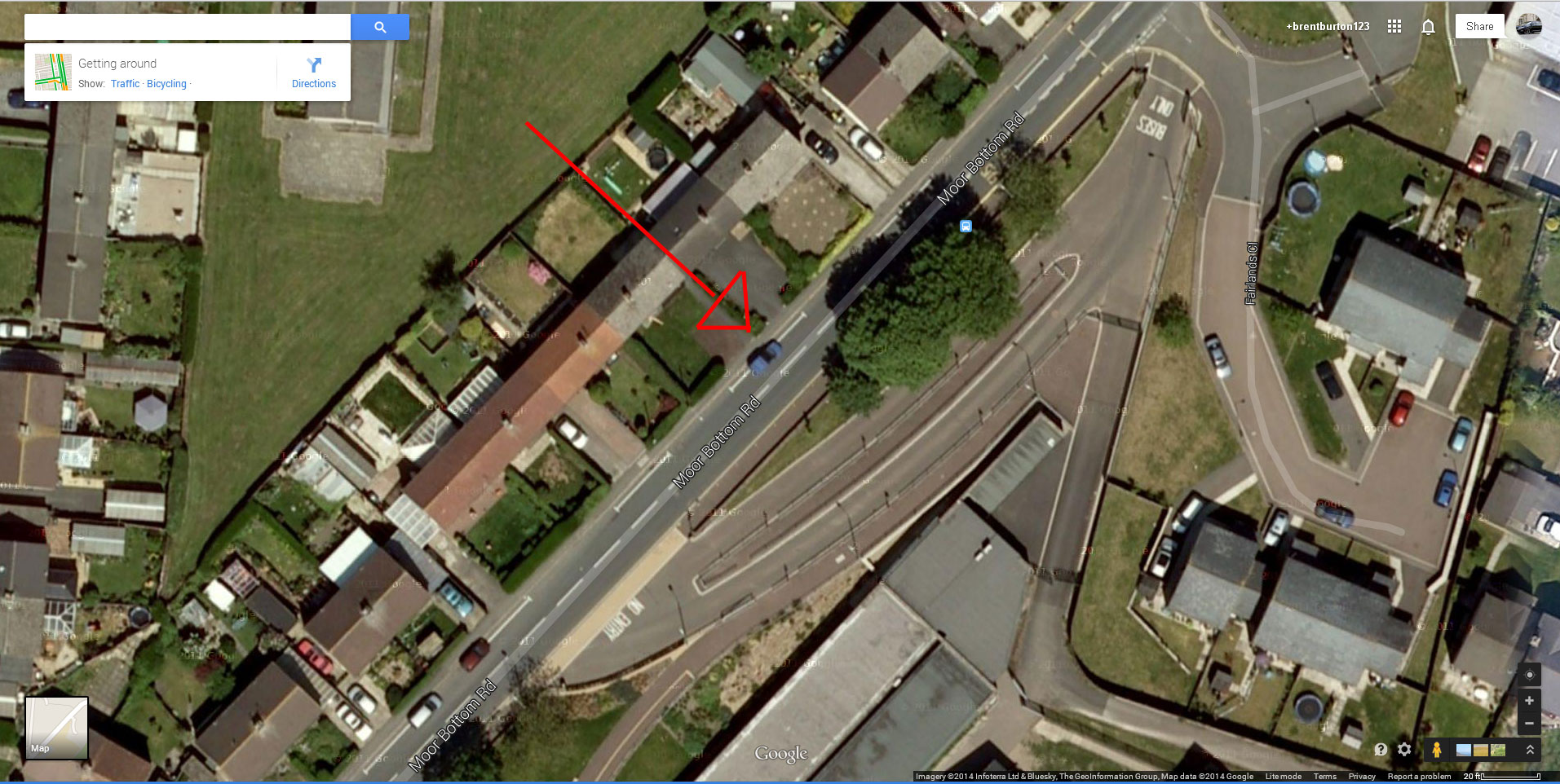
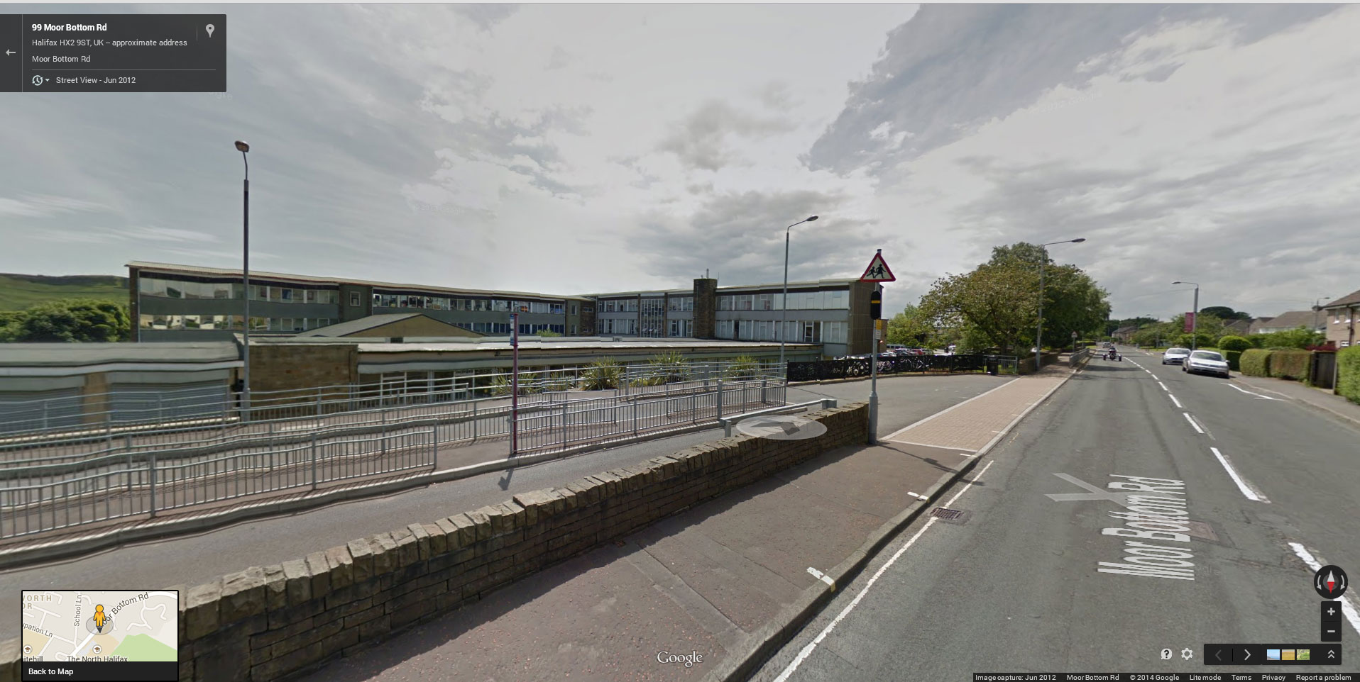
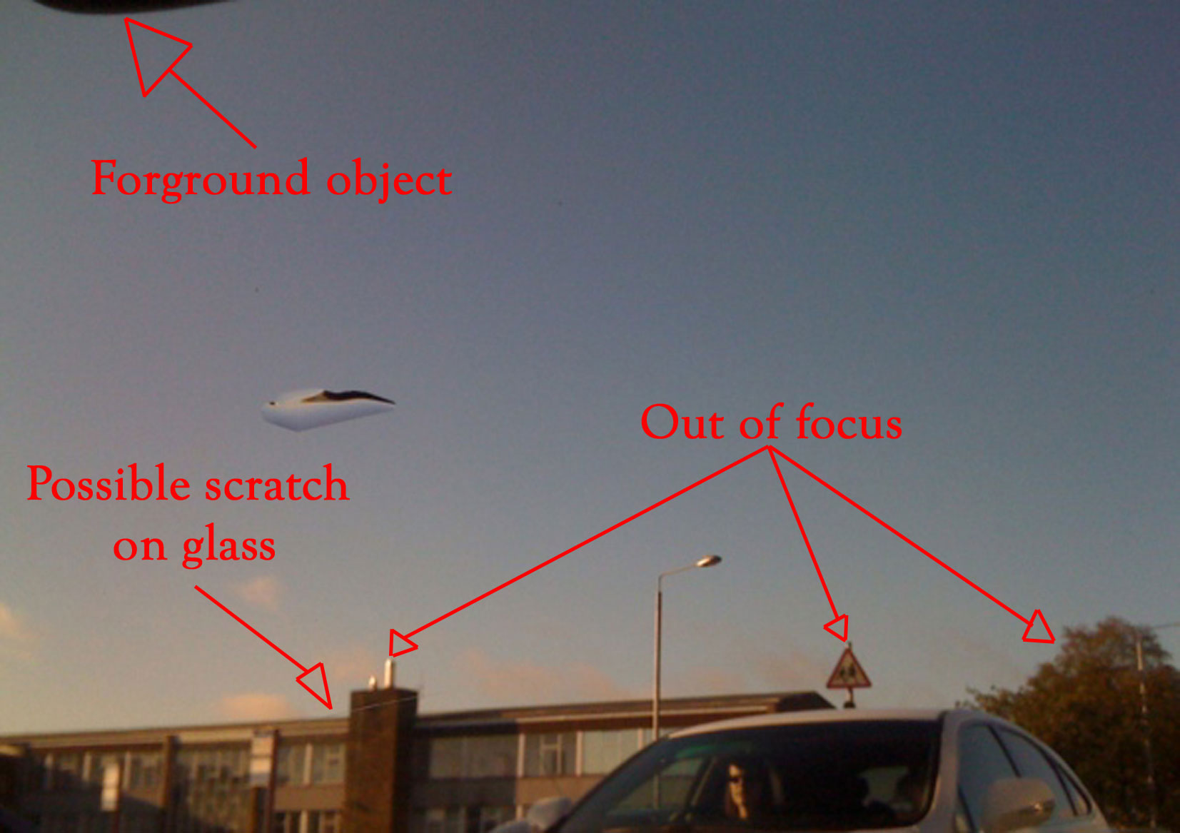
What leads me to believe that the photo was taken from a vehicle and possible through the passenger side glass was the object seen in the upper left corner of the frame (possible some part of the vehicle) and the small hair line that can be seen running through the chimney of the background building. There shouldn't be any power line or other object that can create what is seen there.
Also, it is my opinion that the object in the sky is the ONLY thing that is in sharp focus in the frame. When the photograph is enlarged it is clear that the background objects (building, sign, trees, ect.) are slightly out of focus and do not match the focus level of the object in the sky.
Thank you for your in depth description of the airship concept as described in the Boeing patent. Very informative.
On a side note, your writing style seams very familiar to me as well. As if I've read something of yours before, although, it Seams That my Recollection isn't what it used to be. Sometimes it's zero.
Upon closer examination of the photograph, yes you are absolutely correct that the photo wasn't taken through the wind shield of a car.
Fortunately the eye witness gave a general description of the location. I was able to use that to find a fairly precise orientation of the photographer through Google maps. She would have been almost the same position as the blue car seen bellow:
What leads me to believe that the photo was taken from a vehicle and possible through the passenger side glass was the object seen in the upper left corner of the frame (possible some part of the vehicle) and the small hair line that can be seen running through the chimney of the background building. There shouldn't be any power line or other object that can create what is seen there.
Also, it is my opinion that the object in the sky is the ONLY thing that is in sharp focus in the frame. When the photograph is enlarged it is clear that the background objects (building, sign, trees, ect.) are slightly out of focus and do not match the focus level of the object in the sky.
Thank you for your in depth description of the airship concept as described in the Boeing patent. Very informative.
On a side note, your writing style seams very familiar to me as well. As if I've read something of yours before, although, it Seams That my Recollection isn't what it used to be. Sometimes it's zero.
edit on 28-8-2014 by Sammamishman because: (no reason given)
a reply to: 1947boomer
thank you for that mate, very informative. I'm going to go do some research on what you have posted.
in your opinion is the craft flying left to right? or the other way.
thank you for that mate, very informative. I'm going to go do some research on what you have posted.
in your opinion is the craft flying left to right? or the other way.
originally posted by: lambchop
a reply to: 1947boomer
thank you for that mate, very informative. I'm going to go do some research on what you have posted.
in your opinion is the craft flying left to right? or the other way.
As I said, to me the upper profile of the object look like a 20% thick NACA airfoil, with a circular arc nose on the left and a relatively "sharp" trailing edge on the right side. (It's as sharp as you can get, anyway, with an inflatable structure.) That would mean that the object was intended to fly from the right to the left, while generating lift.
I first saw this photo a couple of years ago, when it came out and I immediately began reverse engineering it, for fun. In addition to the features I've already mentioned, there is one other feature that deserves comment. As you would expect from a HALE platform that was meant to be either a comm relay or a radar surveillance platform, the large antenna would need to be directed into the nadir, or downward hemisphere. More specifically, I would expect the antenna to be steerable to plus and minus 90 degrees around the nadir. That would allow it to send and receive RF power from horizon to horizon. That means the radome, which would be one of the largest elements on the craft would have to be on the bottom surface. I've already suggested that the logical place to locate it is at the 1/4 chord, in order to make the trim problem as minimal as possible.
If you look at the bottom profile, it is triangular, not circular--implying that the radome is a cone, not a hemisphere. Why would this be? Basically, because a hemisphere is a cambered surface and therefore a lifting surface, when placed into a transverse airstream. In this case, because it has to be on the bottom surface, it would generate negative lift, if it were a hemisphere. We airplane designers are taught that positive lift is good, negative lift is bad, and to be avoided if at all possible. Unlike a hemisphere, a cone does not generate lift, when exposed to a transverse airstream--it generates drag only.
Pretty much every observable feature on this image has a functional explanation in line with the kind of vehicle described in the Boeing patent. If this was simply a hoaxer trying to impress everyone with his CGI skills, I don't think there would be this level of arcane, technical detail.
a reply to: 1947boomer
Interesting, are you able to draw a front top planform or some other schematic of the full craft you are seeing in the image?
Interesting, are you able to draw a front top planform or some other schematic of the full craft you are seeing in the image?
a reply to: Sammamishman
I do not in any way consider myself a photography expert, but this sounds like a good analysis to me.
If the photo was taken through a side window glass, does that imply that the camera was manually focused? I would assume that an autofocus algorithm might be fooled by proximity to a piece of glass.
Also, would the close proximity of the glass and perhaps its angle to the camera explain the pattern of focus? When I look at the ridgeline of the building roof in the background, I notice that there is a spot right under the image of the object where the ridgeline appears to change focus. In front of that spot (i.e., closer to the camera) the ridgeline is in better focus and beyond that spot it is quite a bit fuzzier. There is no particular reason to think that the window glass would be at exactly right angles to the camera line of sight. If the camera line of sight went through the window glass at some angle, I would think that the refraction angle might cause some image aberration.
a reply to: 1947boomer
I am by no means a photography expert either. So maybe the camera attempted to come up with a happy medium between the glass (if it was indeed there) and the background. I'm not educated enough in the workings of auto focus to say. If the camera the witness used was of a manual focus type, then it really comes down to the aperture setting and the lens type. Unfortunately there aren't more photographs of the object.
I can only say what I would do if in the shoes of the photographer, viewing this object as long as was reported. I would have as many shots of it from as many angles as my memory chip would hold, dump them on a file share site and wait till MIB came knocking.
originally posted by: Sammamishman
a reply to: 1947boomer
Interesting, are you able to draw a front top planform or some other schematic of the full craft you are seeing in the image?
Not really. The only thing we can infer is that this is an all-wing lifting body. The planform would have to be relatively pointy at the front and broad at the rear--basically, a delta. However, I can't really see anything to indicate what the sweep angle would be. These things would intrinsically have to fly at low subsonic speeds, so there would be no aerodynamic reason to have highly swept wings. On the other hand, hybrid LTA/HTA aircraft typically operate at very low lift coefficients. That tends to decrease the advantage of going to high aspect ratio wings. (Think about it--a blimp uses aerodynamic lift to augment its bouyant lift in exactly the same way this vehicle would, and a blimp's aspect ratio is less than 1. So I would GUESS that this might be pretty close to a classic 60 degree equilateral triangle.
Think that this is just a bit of clever advertising and a bit of a joke that they have starships, rather than some subtle sleight-of-hand to make us
all prepared for future news that we have starships.
Just a thought. Might this somehow be linked to project ICAN or PROJECT AIMStar. Just a wild stab in the dark
a reply to: sputniksteve
"a reply to: DietJoke
Why thank you! I have authored very few threads over my career here, but I am certain I have never had anyone say "Star and Flag" on any of them. I greatly appreciate it. I can't take credit for any of the interesting discussion though, that goes to the posters. Thanks for your thread link, I think that establishes that the guesses of Navy must be correct!
On a side note, I can't believe Zorgon is banned. Seems like a whole slew of old guard all got banned in the last year, lots of posters that were very active and well know. Sad to see them go. I am always surprised to go through older threads and see those names banned. Many of them really confound me."
Oh, I wouldn't worry too much about them...
I have it on good word that they were taken off-world to the DSOTM Elysium style utopia as a reward for being just all around good people. Some of them at least. The ones who were generally good natured and who were well liked. The ones who were jerks were sent to that one prison from the movie Chronicles of Riddick.
BTW, great thread, scubasteve!
a reply to: Zaphod58
Download still works, just finished it and starting to listen now.
Ive been re-reading these interconnected threads for a few days and Im still pulling out things that didn't stand out the first time. Also it seems many are on the same sub-conscious page because as I think ive gotten to an Ah-Ha moment I click to the next page to see others were there months ago. I suppose I`m reflecting my avatar to current specs, as one member has put it in one of these threads. "What were those Blackbird pilots doing, walking?" Ha that cracks me up.
originally posted by: sputniksteve
a reply to: Zaphod58
I will be thinking and watching then. As usual. It is thanks to this section of the forum that I even caught this I believe.
I just can't for the life of me think why USAF would have "star ships" in it's commercial at all to the point that no one during editing stopped to say something. It had to be approved, so it was on purpose. As a civilian rere I assume that Starships isn't even in their vocabulary.
Maybe this: www.dtic.mil/cgi-bin/GetTRDoc?AD=ADA559974
By the way, Marc Millis heads up the Tau Zero foundation and is part of the 100 Year Starship Organization.
edit on 8-1-2015 by JadeStar because: (no reason given)
I still think the government and military industrial complex wants people to think the Air Force would have "Starships".
I think the only "Starship" the AF would have is the Starship Greatest Hits on cassette. Might make for some good tunes to fly around to.
I think the only "Starship" the AF would have is the Starship Greatest Hits on cassette. Might make for some good tunes to fly around to.
a reply to: MystikMushroom
Whats up in your opinion on all the patches associated with US Space Command whether it be AF or Navy that all have a grey triangle in orbit zipping around the earth depicted?
They really like the star trek logo? Alluding to triangular platforms that are earth orbit capable? Just a cool random thing to put on all their patches? Some sort of disinfo trickery? Something completely mundane and I'm looking too into it?
a reply to: sputniksteve
are you #ing nut? the military as an establishment has been lying to young people for hundreds of years with crazy promises. common, this is obviously a no brainier.
are you #ing nut? the military as an establishment has been lying to young people for hundreds of years with crazy promises. common, this is obviously a no brainier.
Yeah cause they use those same triangle shaped icons on patches that are known to be ordinary satellites. Ill have to agree with Mystik here.
a reply to: sputniksteve
Wait a minute.... why has the airforce not cut that 'starship" part out? Or re-do the entire commercial.
This commercial is obviously made for pre-teens. You know... saying the magic word will catch their attention. Mind you ..the attention span of an eight year old is less than 5 seconds and we were already 6 seconds in the commercial when he dropped the word.
Orrrrrrr.... this guy doesn't know what he is talking about and just a hired actor. (false flag operation )
new topics
-
WF Killer Patents & Secret Science Vol. 1 | Free Energy & Anti-Gravity Cover-Ups
General Conspiracies: 14 minutes ago -
Hurt my hip; should I go see a Doctor
General Chit Chat: 1 hours ago -
Israel attacking Iran again.
Middle East Issues: 2 hours ago -
Michigan school district cancels lesson on gender identity and pronouns after backlash
Education and Media: 2 hours ago -
When an Angel gets his or her wings
Religion, Faith, And Theology: 3 hours ago -
Comparing the theology of Paul and Hebrews
Religion, Faith, And Theology: 3 hours ago -
Pentagon acknowledges secret UFO project, the Kona Blue program | Vargas Reports
Aliens and UFOs: 4 hours ago -
Boston Dynamics say Farewell to Atlas
Science & Technology: 5 hours ago -
I hate dreaming
Rant: 5 hours ago -
Man sets himself on fire outside Donald Trump trial
Mainstream News: 7 hours ago
top topics
-
The Democrats Take Control the House - Look what happened while you were sleeping
US Political Madness: 8 hours ago, 18 flags -
In an Historic First, In N Out Burger Permanently Closes a Location
Mainstream News: 10 hours ago, 16 flags -
A man of the people
Medical Issues & Conspiracies: 15 hours ago, 11 flags -
Biden says little kids flip him the bird all the time.
Politicians & People: 7 hours ago, 8 flags -
Man sets himself on fire outside Donald Trump trial
Mainstream News: 7 hours ago, 7 flags -
Pentagon acknowledges secret UFO project, the Kona Blue program | Vargas Reports
Aliens and UFOs: 4 hours ago, 6 flags -
Israel attacking Iran again.
Middle East Issues: 2 hours ago, 5 flags -
Michigan school district cancels lesson on gender identity and pronouns after backlash
Education and Media: 2 hours ago, 4 flags -
4 plans of US elites to defeat Russia
New World Order: 17 hours ago, 4 flags -
Boston Dynamics say Farewell to Atlas
Science & Technology: 5 hours ago, 4 flags
active topics
-
Israel attacking Iran again.
Middle East Issues • 22 • : Boomer1947 -
WF Killer Patents & Secret Science Vol. 1 | Free Energy & Anti-Gravity Cover-Ups
General Conspiracies • 1 • : WakeofPoseidon -
Hurt my hip; should I go see a Doctor
General Chit Chat • 8 • : Dandandat3 -
The Democrats Take Control the House - Look what happened while you were sleeping
US Political Madness • 67 • : WeMustCare -
Thousands Of Young Ukrainian Men Trying To Flee The Country To Avoid Conscription And The War
Other Current Events • 53 • : ghandalf -
Boston Dynamics say Farewell to Atlas
Science & Technology • 5 • : Caver78 -
Biden says little kids flip him the bird all the time.
Politicians & People • 16 • : stelth2 -
When an Angel gets his or her wings
Religion, Faith, And Theology • 2 • : stelth2 -
MULTIPLE SKYMASTER MESSAGES GOING OUT
World War Three • 51 • : Zaphod58 -
Pentagon acknowledges secret UFO project, the Kona Blue program | Vargas Reports
Aliens and UFOs • 7 • : Ophiuchus1