It looks like you're using an Ad Blocker.
Please white-list or disable AboveTopSecret.com in your ad-blocking tool.
Thank you.
Some features of ATS will be disabled while you continue to use an ad-blocker.

The 10 Most Important Inventions of Nikola Tesla... Known (my add)
page: 6share:
a reply to: tanka418
LOL. Keep pretending to be an electrical engineer.
Are you able to disprove Texas Instruments? Do you think Texas Instruments are wrong?
Conduction losses are low because the forward voltage drop accross an IGBT is typically on the order of 2V. If you are switching a battery voltage of 500V, that's 0.4% voltage drop accross the IGBT. No I^2*R losses since IGBTs have BJT like, non-linear output characteristics. Switching losses are low because the parasitic inductance and capacitance of a properly designed inverter powerstage is very low. In addition, proper gate-drive circuitry should charge and discharge the gate capacitance quickly. Both of these factors minimize the time spend when both current through and voltage accross an IGBT are non-zero and therefore minimize switching loss. This allows PWM to be implemented with very high efficiency as shown by datasheets for inverters and motor controllers for electric vehicles:
www.brusa.eu...
tritium.com.au...
www.semikron.com...
Do you think three inverter manufacturers are wrong? What do you base this on?
Watercooling is usually required, but the amount of heat dissipated is still relatively low compared to a combustion engine. The heatsinks required are therefore rather trivial.
Do you? It doesn't seem like it. Then again, you don't seem to know much about anything, do you? Are you going to respond with more inane pedantry?
How so? More inane pedantry. Also in one of the datasheets above is a H-bridge in an inverter.
The requirements for your little Arduino are a little different to what high power inverters need.
www.irf.com...
It's brakes, not breaks. And the brakes on the Model S are doing just fine - actually since brakes are required less due to regenerative braking, the brakes will likely last longer. In any case, they are only used for this purpose if the car needs it, like with aggressive driving. Also plenty of modern cars have similar driving aids. Maybe you should just live as a hermit and only drive old cars then?
No, direction of rotation depends on the phase sequence of the supply lines. Swap two and the induction motor will spin in reverse. With a DSP controlled inverter, this can be done easily in software.
www.moeller.es.../142/MSC.DS.MMAX.ver968en.pdf
www.geekinterview.com...
Are you going to continue making nonsense up or are you going to stop and realize your wrong? Do I have to create a list of all the things you're been wrong at?
LOL. Keep pretending to be an electrical engineer.
As we have all said: BLDC = brushless DC motor...is there some part of DC you didn't get?
This motor is referred to as a "DC" motor because its coils are driven by a DC power source which is applied to the various stator coils in a predetermined sequential pattern. This process is known as commutation. However, "BLDC" is really a misnomer, since the motor is effectively an AC motor. The current in each coil alternates from positive to negative during each electrical cycle. The stator is typically a salient pole structure which is designed to produce a trapezoidal back-EMF waveshape which matches the applied commutated voltage waveform as closely as possible. However, this is very hard to do in practice, and the resulting back-EMF waveform often looks more sinusoidal than trapezoidal. For this reason, many of the control techniques used with a PMSM motor (such as Field Oriented Control) can equally be applied to a BLDC motor.
The most common BLDC motor topology utilizes a stator structure consisting of three phases. As a result, a standard 6-transistor inverter is the most commonly used power stage, as shown in the diagram. Depending on the operational requirements (sensored vs. sensorless, commutated vs. sinusoidal, PWM vs. SVM, etc.) there are many different ways to drive the transistors to achieve the desired goal, which are too numerous to cover here. This places a significant requirement on the flexibility of the PWM generator, which is typically located in the microcontroller. The good news is that all of these requirements are easily achieved in TI's motor control processors.
Brushless DC Motors (BLDC) - Overview Motor Control - Brushless DC (BLDC) Motors - Texas Instruments
www.ti.com...
Are you able to disprove Texas Instruments? Do you think Texas Instruments are wrong?
Oh, oh...I wanted to hear "why" inverters are so efficient...
Conduction losses are low because the forward voltage drop accross an IGBT is typically on the order of 2V. If you are switching a battery voltage of 500V, that's 0.4% voltage drop accross the IGBT. No I^2*R losses since IGBTs have BJT like, non-linear output characteristics. Switching losses are low because the parasitic inductance and capacitance of a properly designed inverter powerstage is very low. In addition, proper gate-drive circuitry should charge and discharge the gate capacitance quickly. Both of these factors minimize the time spend when both current through and voltage accross an IGBT are non-zero and therefore minimize switching loss. This allows PWM to be implemented with very high efficiency as shown by datasheets for inverters and motor controllers for electric vehicles:
www.brusa.eu...
tritium.com.au...
www.semikron.com...
Do you think three inverter manufacturers are wrong? What do you base this on?
I'll just ask...what happens to all the heat?
Watercooling is usually required, but the amount of heat dissipated is still relatively low compared to a combustion engine. The heatsinks required are therefore rather trivial.
PWM?!!??? Do you even know what that is? Seriously, do you?
Do you? It doesn't seem like it. Then again, you don't seem to know much about anything, do you? Are you going to respond with more inane pedantry?
You should go an look up an "H-bridge"...its not quite what you think
How so? More inane pedantry. Also in one of the datasheets above is a H-bridge in an inverter.
Practically speaking, control of a 3-phase AC induction motor requires pulse-width modulated control of the six switches of a 3-phase inverter bridge connected to the motor’s stator windings (Figure 1). The six switches form 3 pairs of “half-bridges”, which can be used to connect the leg of a winding to the positive or the negative high-voltage DC bus.
www.microchip.com...
using a bipolar transistor in a case like this? Well, let me just say; I must have been doing software too long...I would NEVER use a bipolar transistor in an application like this. The use of field effect technology seems a better choice.
The requirements for your little Arduino are a little different to what high power inverters need.
www.irf.com...
Wow! Really!?? Ya know I was thinking about getting a Tesla Roadster, but, IF they are controlling individual wheels with the breaks...I don't want one...the breaking system will be unreliable, and over used. It will experience excessive wear to breaking components. Probably break fade after only a little use...
It's brakes, not breaks. And the brakes on the Model S are doing just fine - actually since brakes are required less due to regenerative braking, the brakes will likely last longer. In any case, they are only used for this purpose if the car needs it, like with aggressive driving. Also plenty of modern cars have similar driving aids. Maybe you should just live as a hermit and only drive old cars then?
AC motors typically have only one direction of rotation, depending on how they are "wound". This is because AC involves the reversal of current flow typically for 50% of the duty cycle. IF we were to wind a motor so that we could use a controller to reverse the direction of the magnetic field movement; then we would no longer have an "AC induction" motor, we would have something else.
No, direction of rotation depends on the phase sequence of the supply lines. Swap two and the induction motor will spin in reverse. With a DSP controlled inverter, this can be done easily in software.
www.moeller.es.../142/MSC.DS.MMAX.ver968en.pdf
www.geekinterview.com...
The method of changing the direction of rotation of an induction motor depends on whether it is a three-phase or single-phase machine. In the case of three phase, reversal is carried out by swapping connection of any two phase conductors. In the case of a single-phase motor it is usually achieved by changing the connection of a starting capacitor from one section of a motor winding to the other. In this latter case both motor windings are similar (e.g. in washing machines).
en.wikipedia.org...
Are you going to continue making nonsense up or are you going to stop and realize your wrong? Do I have to create a list of all the things you're been wrong at?
edit on 2/6/14 by C0bzz because: (no reason given)
edit on 2/6/14 by C0bzz because: (no reason given)
a reply to: C0bzz
You do know; that in a typical old school DC motor...you know...One with a PM field...the current in the armature is AC "like" right. In that as the armature rotates the brushes change the direction of current flow in the armature.
Just like your BLDC motor, this current is not AC. AND, there was no inverter involved.
TI and it appears many others are "stretching" reality when they attempt to explain the actions of these DC motors. They do this by equating it to AC, when, in reality, there is no AC involved...that is to say; that while the voltage and current may behave like AC, it is, in reality, only pulsed DC. You need to understand something...AC means alternating current; A current which periodically reverses its direction of flow...this is accompanied by an alternation of polarity of the voltage.
In a system like you are talking about...current never changes direction...it is applied, and removed, as in through a switch. Just like your H-bridge... current does not flow in alternating directions from the current source, though it may be applied in an intelligent manner (time delayed so as to function like a different AC phase...can even be thought of as a "phase" even though it really isn't).
You need to find some educational materials that are at your level of comprehension, as opposed to these that someone tried and failed to "dumb down" for your consumption. A real education on these matters will serve you well, and help you get around the BS that some technical writers seem to like to throw around.
IF you will do that; I'll go back to my data analysis software and we can be just fine...
a reply to: tanka418
No, the resources I provided were very clear. If you measure the current of a phase of a BLDC motor, it will be very clear that the direction of current does change direction. This was very clearly illustrated on the TI website. Since a BLDC motor only has 3 connections, one for each phase, and due to KCL, it's impossible for the polarity not to periodically be reversed.
Let's go back and see all the nonsensical things you said or implied...:
1. Induction motors can only operate in one direction.
2. Inverters are 70% efficient.
3. DC motors are significantly more efficient than AC motors.
4. Induction Motors are not really AC and instead use "sliced DC".
5. Tesla doesn't use an inverter to control an induction motor and instead use "sliced DC".
6. Tesla Motors uses gears.
7. BLDC motors don't require inverters.
8. PMSM motors don't require AC.
9. Torque vectoring using brakes will result in excessive brake wear.
10. Electric Vehicles should have an electric motor on each wheel for efficiency.
11. Current only flows in one direction in a BLDC motor.
12. Texas Instruments are misleading (pretty clear to me?)
And then rather than admit you were wrong after getting a dozen things wrong, you end with:
I don't see how you can expect a civil reply? It's time to admit you have been focusing on software for far too long and therefore know very little about electrical engineering. And that you were wrong. Also quit assuming you know anything about my education, I prefer not to divulge that information on conspiracy websites.
TI and it appears many others are "stretching" reality when they attempt to explain the actions of these DC motors. They do this by equating it to AC, when, in reality, there is no AC involved...that is to say; that while the voltage and current may behave like AC, it is, in reality, only pulsed DC.
No, the resources I provided were very clear. If you measure the current of a phase of a BLDC motor, it will be very clear that the direction of current does change direction. This was very clearly illustrated on the TI website. Since a BLDC motor only has 3 connections, one for each phase, and due to KCL, it's impossible for the polarity not to periodically be reversed.
Let's go back and see all the nonsensical things you said or implied...:
1. Induction motors can only operate in one direction.
2. Inverters are 70% efficient.
3. DC motors are significantly more efficient than AC motors.
4. Induction Motors are not really AC and instead use "sliced DC".
5. Tesla doesn't use an inverter to control an induction motor and instead use "sliced DC".
6. Tesla Motors uses gears.
7. BLDC motors don't require inverters.
8. PMSM motors don't require AC.
9. Torque vectoring using brakes will result in excessive brake wear.
10. Electric Vehicles should have an electric motor on each wheel for efficiency.
11. Current only flows in one direction in a BLDC motor.
12. Texas Instruments are misleading (pretty clear to me?)
And then rather than admit you were wrong after getting a dozen things wrong, you end with:
You need to find some educational materials that are at your level of comprehension
I don't see how you can expect a civil reply? It's time to admit you have been focusing on software for far too long and therefore know very little about electrical engineering. And that you were wrong. Also quit assuming you know anything about my education, I prefer not to divulge that information on conspiracy websites.
edit on 2/6/14 by C0bzz because: (no reason given)
originally posted by: C0bzz
Let's go back and see all the incorrect things you said or implied...:
1. That induction motors can only operate in one direction.
2. That inverters are 70% efficient.
3. That DC motors are more efficient than AC motors.
4. That Induction Motors are not really AC and instead use "sliced DC".
5. That Tesla doesn't use an inverter to control an induction motor.
6. That Tesla Motors uses gears.
7. That BLDC motors don't require inverters.
8. That PMSM motors don't require AC.
9. That current only flows in one direction in a BLDC motor.
10. That Texas Instruments are misleading (pretty clear to me?)
Sure why don't we...
1. The traditional induction motor does not have a sophisticated controller running it. For instance the motor in your refrigerator; has a capacitor in its starting circuit to increase the amount of start up current...that is the limit of its electric controls other than the power switch (relay).
Any AC motor that is capable of reversing direction has more controller, runs off a multiple phase source...all in all...not much of a traditional "induction" motor. Course IF we relax the term "induction" a bit, our motors will fit.
2. No error there...inverters are notoriously inefficient. You see, they generate large amounts of heat, which MUST be dealt with. Your previous comments on heat sinks was truly funny, since you fail to account for junction temperatures in the control elements.
Tesla autos have a 60kw power supply...the electric motor is substantially less than 60kw, and probably on the order of 35kw - 40kw (the overall system is designed to accommodate 50kw...50kw + 20% = 60kw)...with the power source having to support other functions; I'd guess the actual motor at around 35kw...considerably less than my 1979 280Z.
3. I did not say DC motors wee more efficient than AC motors...that sir is your misunderstanding.
4. Again you misunderstand what I said...an induction can run n anything equivalent to AC...if that is switched DC...it doesn't matter it all works the same.
5. Actually Tesla might use an inverter...but then again, no one said they actually know "how" to design an electric car...The use of switched (pulsed) DC, like in your PC is far more efficient that trying to produce a true AC signal. It is much easier to control the motor with a small computer and the "timely" application of voltage...more efficient too.
6. Yes...beginning with the roadster Tesla has used a two forward, one reverse gear box. Although, it appears that they have removed the gearbox and have opted for motor control to replace that function. I'm an old school sports car type...would never work for me.
7. BLDC...again what part of Direct Current do you not understand? The "switching" of DC does not always constitute AC. And, just like the reversal of current in an old school brushed DC motor, there is no "AC" involved.
8. Again, while this is difficult for you to comprehend, Pulses of DC are not the same as AC...
9. I never said that...IF you think I did it is you not understanding what I said...your bad!
10. Technical writers do that sort of thing all the time. Partly because they themselves do not have a solid grasp on what they are writing about, and partly because they are writing for YOU...someone who has little, no understanding of the technology. They aren't truly "misleading", but, they do not accurately present the underlying physics either.
And then rather than admit you were wrong after getting almost a dozen things wrong, you end with:
yes and again: "You need to find some educational materials that are at your level of comprehension."
Now, in order to head off some confusion...AC, alternating current. is a phenomena where polarity of applied voltage is periodically reversed, causing a change in direction of current flow. This results in a reversal of magnetic field. This prevents DC motors from working by the way.
In induction, current is said to be induced into a conductor when it "cuts" magnetic lines of force...this is what makes motors, generators, alternators, etc. work. Induction does not require the reversal of magnetic fields to operate...only the changing of that field relative to the conductor. Ya got that? If either the conductor or the magnetic field moves, current is induced. SO...to operate that "induction" motor does not require AC, only a good equivalent, which switched DC does quite well.
Now then about all that heat...What happens to it, again? What kind of "thermal envelope" do you suppose the control elements have? You are right in one small regard; I have been away from this kind of electronics for a long while; though, that still does not change any of the physics involved. So, I can only compare those power control elements to computer electronics...don't worry, the comparison is valid. My i7 is a bit old and has a 135w thermal envelope (you would need several times that value in the Tesla application). Under normal circumstances; the system will not run long enough to "boot" withoout a heat sink and fan on that i7. My computer does not have to worry about more than 600watts of power...that Tesla has 60,000 watts of energy. So...about those control elements. Necessarily; there are many, they generate great amounts of heat, that heat must be dissipated...which requires additional energy...sorry man; it's the nature of the beast.
Nice of ya to change things up like ya did; so here are your confused responses.
Yes...using the brakes to control wheel rpm is an absolutely STUPID ides. It WILL result is additional wear, and over the lifetime of the vehicle will add to total cost of ownership...So..not a good idea.
Yes again; a motor on each wheel...say 40% the size of the Tesla motor would produce a car that has better overall performance, and safety.
edit on 2-6-2014 by tanka418 because: (no reason given)
Credit where credit is due : Tesla coils make impressive loudspeakers ...
youtube.com/watch?v=hgll-XTqcS4
youtube.com/watch?v=hgll-XTqcS4
edit on 2-6-2014 by engvbany because: (no reason
given)
a reply to: tanka418
This conversation is about electric vehicles, not refrigerators. In an electric vehicle, precise torque control is required. That means an inverter is required to provide precise control of the motor - namely a variable frequency, 3-phase, variable amplitude drive.
Most large induction motors are also three-phase hence if reverse operation is necessary, simply swapping two of the three phases is all that is necessary to change the direction. This can be done physically or via a software setting on an inverter.
A single phase induction motor doesn't create a rotating magnetic field, it creates an oscillating magnetic field. A capacitor provides a lagging power factor on a second winding in a single phase induction motor, creating a rotating magnetic field at start-up, hence setting the direction of the motor. Changing the second winding configuration can also change the direction of the motor.
You are using junction temperatures like a buzzword. Yes, the fact that there are losses within the transistor doesn't mean they are inefficient. It was also already implicitly mentioned in my previous post when I mentioned switching loss and conduction loss. Conduction loss is caused by the forward voltage of an IGBT or (on) drain-source resistance of a MOSFET. Switching loss is due to the short period of time when switching when neither current nor voltage is (close to) zero. These losses are small as I have shown with three inverter datasheets including two motor controllers designed for electric vehicles, if you feel manufacturers are wrong then please explain that to Tritium, Semikron, Brusa, and more, all of whom will say the same thing.
Power electronics are known to be notoriously efficient.
No, Tesla uses a 60 kWh or 85 kWh battery pack. You are confusing energy and power. The base Tesla Model S has a 270 kW induction motor, higher end models have a 310 kW induction motor. Actually the induction motor is the same between them, but the larger battery can be discharged faster and an upgraded inverter is provided. Also the vehicle is geared so that max power is generated at about 55 mph, under which the vehicle is constant torque. 310 kW for Performance Model - at the wheels.

source: www.teslamotorsclub.com...
A 3-ph induction motor requires 3-ph AC. It can not operate on DC. DC cannot create a rotating magnetic field. I still don't know what you mean by "switched DC", I earlier assumed you meant PWM but your response to that was:
"PWM?!!??? Do you even know what that is? Seriously, do you? "
Do you mean PWM when say you "switched DC"? In any case, fourier analysis will show that any waveform applied to operate an induction motor is AC. PWM is used in inverters to create AC. That's exactly how they work. You seem to call AC generated by via PWM control techniques "pulsed DC". It's really just AC as shown by fourier analysis!
Also inverters and ac-dc power supplies like those in your computer operate the same way. Pulse Width Modulation of switching elements such as MOSFETs!
The "gears" aren't actually gears at all. It has Drive, Park, Neutral, and Reverse. Here's the owners manual.
1. The traditional induction motor does not have a sophisticated controller running it. For instance the motor in your refrigerator; has a capacitor in its starting circuit to increase the amount of start up current...that is the limit of its electric controls other than the power switch (relay).
This conversation is about electric vehicles, not refrigerators. In an electric vehicle, precise torque control is required. That means an inverter is required to provide precise control of the motor - namely a variable frequency, 3-phase, variable amplitude drive.
Most large induction motors are also three-phase hence if reverse operation is necessary, simply swapping two of the three phases is all that is necessary to change the direction. This can be done physically or via a software setting on an inverter.
A single phase induction motor doesn't create a rotating magnetic field, it creates an oscillating magnetic field. A capacitor provides a lagging power factor on a second winding in a single phase induction motor, creating a rotating magnetic field at start-up, hence setting the direction of the motor. Changing the second winding configuration can also change the direction of the motor.
2. No error there...inverters are notoriously inefficient. You see, they generate large amounts of heat, which MUST be dealt with. Your previous comments on heat sinks was truly funny, since you fail to account for junction temperatures in the control elements.
You are using junction temperatures like a buzzword. Yes, the fact that there are losses within the transistor doesn't mean they are inefficient. It was also already implicitly mentioned in my previous post when I mentioned switching loss and conduction loss. Conduction loss is caused by the forward voltage of an IGBT or (on) drain-source resistance of a MOSFET. Switching loss is due to the short period of time when switching when neither current nor voltage is (close to) zero. These losses are small as I have shown with three inverter datasheets including two motor controllers designed for electric vehicles, if you feel manufacturers are wrong then please explain that to Tritium, Semikron, Brusa, and more, all of whom will say the same thing.
Power electronics are known to be notoriously efficient.
Tesla autos have a 60kw power supply...the electric motor is substantially less than 60kw, and probably on the order of 35kw - 40kw (the overall system is designed to accommodate 50kw...50kw + 20% = 60kw)...with the power source having to support other functions; I'd guess the actual motor at around 35kw...considerably less than my 1979 280Z.
No, Tesla uses a 60 kWh or 85 kWh battery pack. You are confusing energy and power. The base Tesla Model S has a 270 kW induction motor, higher end models have a 310 kW induction motor. Actually the induction motor is the same between them, but the larger battery can be discharged faster and an upgraded inverter is provided. Also the vehicle is geared so that max power is generated at about 55 mph, under which the vehicle is constant torque. 310 kW for Performance Model - at the wheels.
source: www.teslamotorsclub.com...
4. Again you misunderstand what I said...an induction can run n anything equivalent to AC...if that is switched DC...it doesn't matter it all works the same.
A 3-ph induction motor requires 3-ph AC. It can not operate on DC. DC cannot create a rotating magnetic field. I still don't know what you mean by "switched DC", I earlier assumed you meant PWM but your response to that was:
"PWM?!!??? Do you even know what that is? Seriously, do you? "
Do you mean PWM when say you "switched DC"? In any case, fourier analysis will show that any waveform applied to operate an induction motor is AC. PWM is used in inverters to create AC. That's exactly how they work. You seem to call AC generated by via PWM control techniques "pulsed DC". It's really just AC as shown by fourier analysis!
Also inverters and ac-dc power supplies like those in your computer operate the same way. Pulse Width Modulation of switching elements such as MOSFETs!
6. Yes...beginning with the roadster Tesla has used a two forward, one reverse gear box. Although, it appears that they have removed the gearbox and have opted for motor control to replace that function.
The wide torque band, particularly the torque available at low RPM, eliminates the need for gears – the Roadster has only a single speed gear reduction; one gear ratio from zero to top speed. Switch two of the phases (this can be done electronically), and the motor runs in reverse. No need for a reverse gear.
www.teslamotors.com...
The "gears" aren't actually gears at all. It has Drive, Park, Neutral, and Reverse. Here's the owners manual.
edit on 6/6/14 by C0bzz because: (no reason
given)
7. BLDC...again what part of Direct Current do you not understand? The "switching" of DC does not always constitute AC.
Each winding in a 3-ph BLDC motor is separated by 120 degrees electrically. The polarity of the windings must be periodically changed depending on the physical orientation of the rotor so that the applied voltage is in-phase with the back-EMF. In addition, the voltage applied must be variable to provide torque / speed control. All these are reasons why an inverter is necessary, as described by the TI article.
This meets your own description of "AC" which I have provided below:
AC, alternating current. is a phenomena where polarity of applied voltage is periodically reversed, causing a change in direction of current flow. This results in a reversal of magnetic field.
Moroever, fourier analysis of the waveforms generated or applied to operate a BLDC motor will show quiet clearly that there is no DC component to the frequency spectra. Periodically switching a DC-bus to create a square wave creates an AC signal with a huge amount of harmonic content. Using PWM at a few kHz and filtering creates a AC signal with less harmonics.
edit on 6/6/14 by C0bzz because: (no reason given)
edit on 6/6/14 by C0bzz because: (no reason given)
Now then about all that heat...What happens to it, again? What kind of "thermal envelope" do you suppose the control elements have? You are right in one small regard; I have been away from this kind of electronics for a long while; though, that still does not change any of the physics involved. So, I can only compare those power control elements to computer electronics...don't worry, the comparison is valid. My i7 is a bit old and has a 135w thermal envelope (you would need several times that value in the Tesla application). Under normal circumstances; the system will not run long enough to "boot" withoout a heat sink and fan on that i7. My computer does not have to worry about more than 600watts of power...that Tesla has 60,000 watts of energy. So...about those control elements. Necessarily; there are many, they generate great amounts of heat, that heat must be dissipated...which requires additional energy...sorry man; it's the nature of the beast.
www.infineon.com...
Check the Thermal Resistance, Junction to Case and Case to Heatsink and app notes. That thing is a bit monstrous though, might be used in a power station rather than a car.
The Semikron inverter I linked was air cooled and was designed for 140 kW and had a 300 W fan. 0.2% Efficiency Loss. The Brusa & Tritium I linked earlier had some of their own specifications, but in any case the cooling required was still fairly low, less than 1% efficiency loss.
GOD! the cult of tesla at it again... People should really look into the history of these things before subscribing to the cult of tesla's crazy
ideas about how he invented all this stuff when he didn't...
originally posted by: C0bzz
Please do not ever refer to an inverter output as being "pulsed DC". It's AC created via PWM and the topology of the inverter itself. This can be justified by looking at the frequency spectra of such an inverter.
A somehwhat off-topic question. Suppose you were to have a voltage waveform, and hence current, which was always positive, but time-dependent, for example a square wave or sine wave with a minimum at zero.
Applied to a load, the charge carriers would only be going in one direction, but with velocity which changes with time with the applied voltage.
In your practice, is this type of signal described as in the category of "AC" or "DC"? In some ways the current is changing, but not alternating in direction or sign. I am aware of spectral decompositions, and without the 0 frequency term the signal is obviously AC.
So in common use, does DC now really mean 'essentially constant in time' (stricter definition of DC, loose of AC) or the other way (AC means zero mean averaged over a period).
I'm not very clever. Who won ? C0bzz or tanka
Maybe the op can change the name of the thread "Top ten important bits of a Tesla Roadster"
Maybe the op can change the name of the thread "Top ten important bits of a Tesla Roadster"
originally posted by: mbkennel
originally posted by: JustXeno
I'm not very clever. Who won ? C0bzz or tanka
C0bzz has more specific and up-to-date knowledge about the technology.
Cobzz read a couple of application notes and thinks himself an engineer. I spent 40+ years working as an engineer, and I think I'm retired.
You figure out which One knows and which doesn't. I'm not arguing with him anymore...my Wolf listens far better, and doesn't "think" himself something he isn't.
a reply to: mbkennel
It depends.
I would consider it an AC signal with DC offset.
However, if the DC component were much bigger than the AC component (e.g. DC-DC converter output with some ripple) then it would be considered DC. Decomposing signals into their components was probably one of the most worthwhile things I was taught.
It depends.
for example a square wave or sine wave with a minimum at zero.
I would consider it an AC signal with DC offset.
However, if the DC component were much bigger than the AC component (e.g. DC-DC converter output with some ripple) then it would be considered DC. Decomposing signals into their components was probably one of the most worthwhile things I was taught.
edit on 7/6/14 by C0bzz because: (no
reason given)
a reply to: tanka418
By your own admission, you do not have experience with electric vehicles or power electronics and are mostly "a computer and software type" and "have been away from this kind of electronics for a long while". Nothing you state is supported by any literature. Meanwhile, everything I have stated here (which is pretty elementary stuff) is supported by extensive literature (believe me, there's a lot more where that came from too).
In addition, I have some experience with electric vehicles - myself and colleagues have already done and/or verified almost everything we have discussed. Uh, the motor controller hasn't melted yet even though the cooling system was designed around >95% efficiency? Generally I don't bring that up because I prefer discussions to focus on the arguments presented themselves, rather than hiding behind supposed "credentials". It's also amusing being told that I have "misconceptions about electric autos, and their technology".
Every time you post you introduce more flaws into this discussion, in your previous post you:
I think we're done here.
Cobzz read a couple of application notes and thinks himself an engineer. I spent 40+ years working as an engineer, and I think I'm retired.
You figure out which One knows and which doesn't. I'm not arguing with him anymore...my Wolf listens far better, and doesn't "think" himself something he isn't.
By your own admission, you do not have experience with electric vehicles or power electronics and are mostly "a computer and software type" and "have been away from this kind of electronics for a long while". Nothing you state is supported by any literature. Meanwhile, everything I have stated here (which is pretty elementary stuff) is supported by extensive literature (believe me, there's a lot more where that came from too).
In addition, I have some experience with electric vehicles - myself and colleagues have already done and/or verified almost everything we have discussed. Uh, the motor controller hasn't melted yet even though the cooling system was designed around >95% efficiency? Generally I don't bring that up because I prefer discussions to focus on the arguments presented themselves, rather than hiding behind supposed "credentials". It's also amusing being told that I have "misconceptions about electric autos, and their technology".
Every time you post you introduce more flaws into this discussion, in your previous post you:
- Stated Tesla has a 60 kW "power source". In reality the base Model S has a 60 kWh battery, which means you confused power and energy, an elementary
mistake.
- Compared a power electronic converter to your desktop PC (despite extensive literature available online on inverter cooling). You could for
example, use the heat capacity of water to show that a relatively small flow rate is required if water cooling were to be used.
- Stated that there are losses within an inverter without any attempt to quantify them and explain why they are significant, despite
significant evidence to the contrary including 3 datasheets. Also here's a
motor drive with 99% efficiency.
I think we're done here.
edit on 7/6/14 by C0bzz because: (no reason given)
originally posted by: C0bzz
I think we're done here.
Indeed! I'm truly sorry you are so mislead on this...not my fauly.
You see; I think I'll continue to rely upon what I was taught at Cal Poly, and Stanford. Despite what seems far superior educational opportunities with your wee circle of friends.
Firlsty; I did not confuse power and energy...and I have very serious reservations as to whether YOU know the real difference.
Second; remember when you were asking about my term "switched DC" (and a couple similar)? That was a wee bit of a "trick". Electronically there is little difference between this "switched DC" and true AC. I did it to test your level of understanding...sorry man...
So; yes indeed we are finished. I would prefer to discuss, rather than argue. A discussion required that both sides have some common ground. I have a lifetime career as an Electrical Engineer / Software Engineer, you have some fantasy filled with typical non-technical pseudo-application notes.
Y'all have a good time.
edit on 7-6-2014 by tanka418 because: (no reason given)
a reply to: tanka418
Simply stating that you do know the difference between power and energy doesn't prove much. The only well-known figure involving the number "60" in any Tesla vehicle is the size of the battery pack of the baseline Model S. Which means you simply confused energy with power, or you simply lied and made the figure up. That makes you one of two things, a liar, or an electrical engineer who doesn't know the difference between power and energy. Which one is it?
I am still waiting for a proper explanation of how "switched DC" isn't AC. You got through Stanford and Cal Poly without knowing the difference between DC and AC?
You lasted 40 years without knowing the difference between power and energy? Wow! I sure hope the software you developed isn't used in anything important.
I hope our future conversations amuse me as much as this one did. I really enjoy telling people how wrong they are. It's also proof for everyone to see - that you have no idea what you're talking about and are unable to provide evidence behind your claims.
Drop the fantasies you have about modern science and technology... they only serve to confine you.
Firlsty; I did not confuse power and energy...and I have very serious reservations as to whether YOU know the real difference.
Simply stating that you do know the difference between power and energy doesn't prove much. The only well-known figure involving the number "60" in any Tesla vehicle is the size of the battery pack of the baseline Model S. Which means you simply confused energy with power, or you simply lied and made the figure up. That makes you one of two things, a liar, or an electrical engineer who doesn't know the difference between power and energy. Which one is it?
Second; remember when you were asking about my term "switched DC" (and a couple similar)? That was a wee bit of a "trick". Electronically there is little difference between this "switched DC" and true AC. I did it to test your level of understanding...sorry man...
I am still waiting for a proper explanation of how "switched DC" isn't AC. You got through Stanford and Cal Poly without knowing the difference between DC and AC?
I have a lifetime career as an Electrical Engineer / Software Engineer,
You lasted 40 years without knowing the difference between power and energy? Wow! I sure hope the software you developed isn't used in anything important.
I hope our future conversations amuse me as much as this one did. I really enjoy telling people how wrong they are. It's also proof for everyone to see - that you have no idea what you're talking about and are unable to provide evidence behind your claims.
Drop the fantasies you have about modern science and technology... they only serve to confine you.
edit on 7/6/14 by C0bzz because: (no reason given)
One of the things I like about this discussion format is that it allows each of us to check our knowledge against reality. I actually do that sort of
thing frequently...that way I "know" what I know...
Anyway that is what I did with these BLDC motors...just to insure I was right...and as usual I am.
Here is how a BLDC motor works:
First we'll start with a rudimentary controller, nothing extravagant, just the basics...
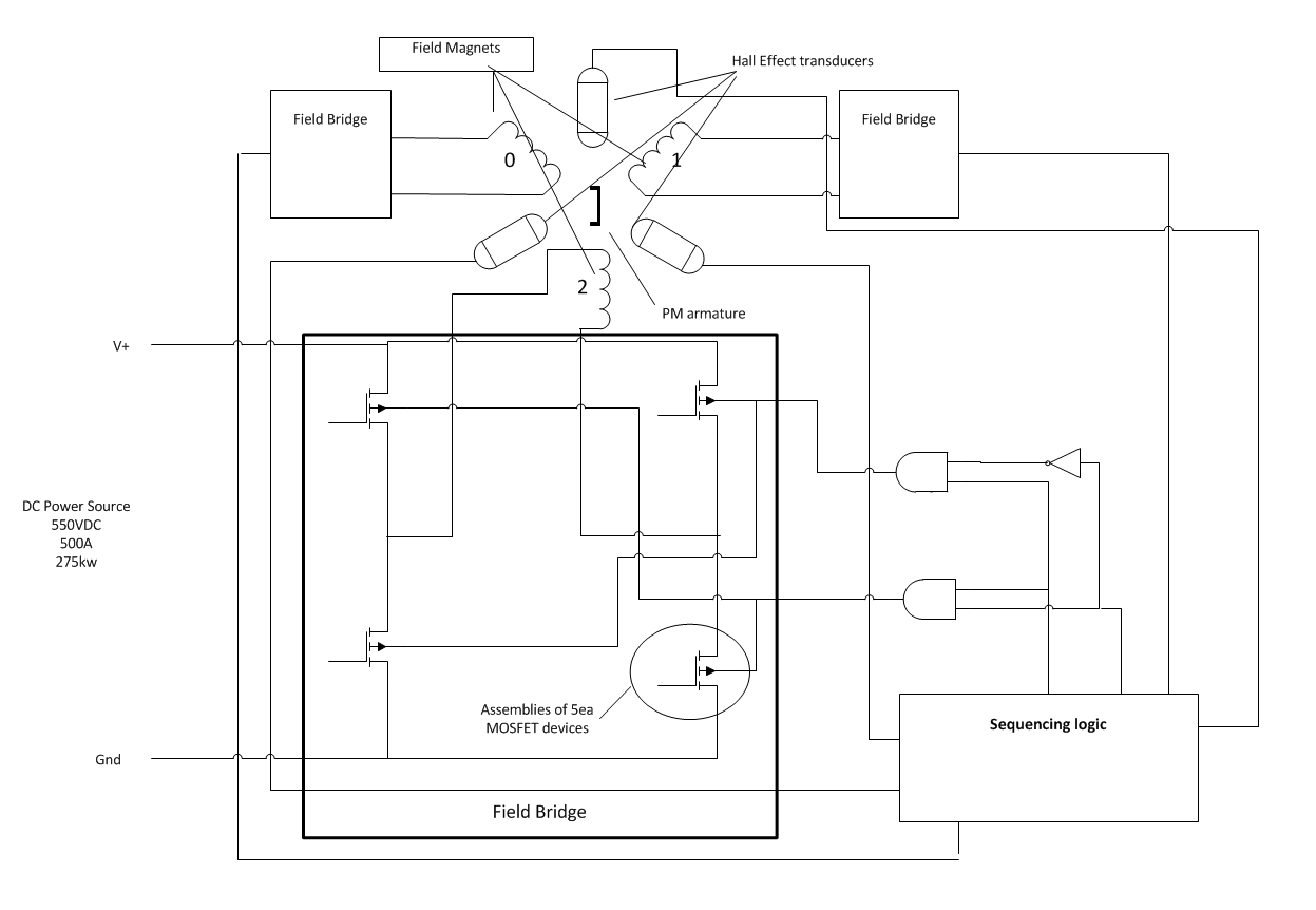
You should notice that only one "field bridge" is illustrated...within this bridge are a few logic elements, and, in our example, 5 MOSFET transistors. These transistors will act as switches for our high voltage, high current "drive" for our three field magnets.
The way this motor works is that the permanent magnet we used to see in our slot car motors has been moved fro the field to the armature, this way we have no need of brushed or current flow in the armature. Solves some issues, has others of its own; like the magnetic field around the armature now must rotate and "drag" the armature along. Doing this efficiently requires precise timing.
That timing is supplied by the "sequencing logic". This part would probably have a microprocessor in it to help with control and interface tasks.
The timing of this beast is quite important...
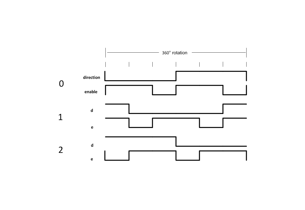
This is where we find it difficult to differentiate between AC and DC. We see our field magnets being driven with what appears to be square waves of some sort, and thus "AC". While under some circumstances, this kind of "switched" waveform may be thought of as "AC", this isn't one of those cases. The real differences that come into play here regarding the "AC" component will not become significant until much higher frequencies are attained, and in this application those frequencies are highly improbable; would indicate something broken).
Here is a series of images showing the state of the field magnets at each of the systems "switching" pints.
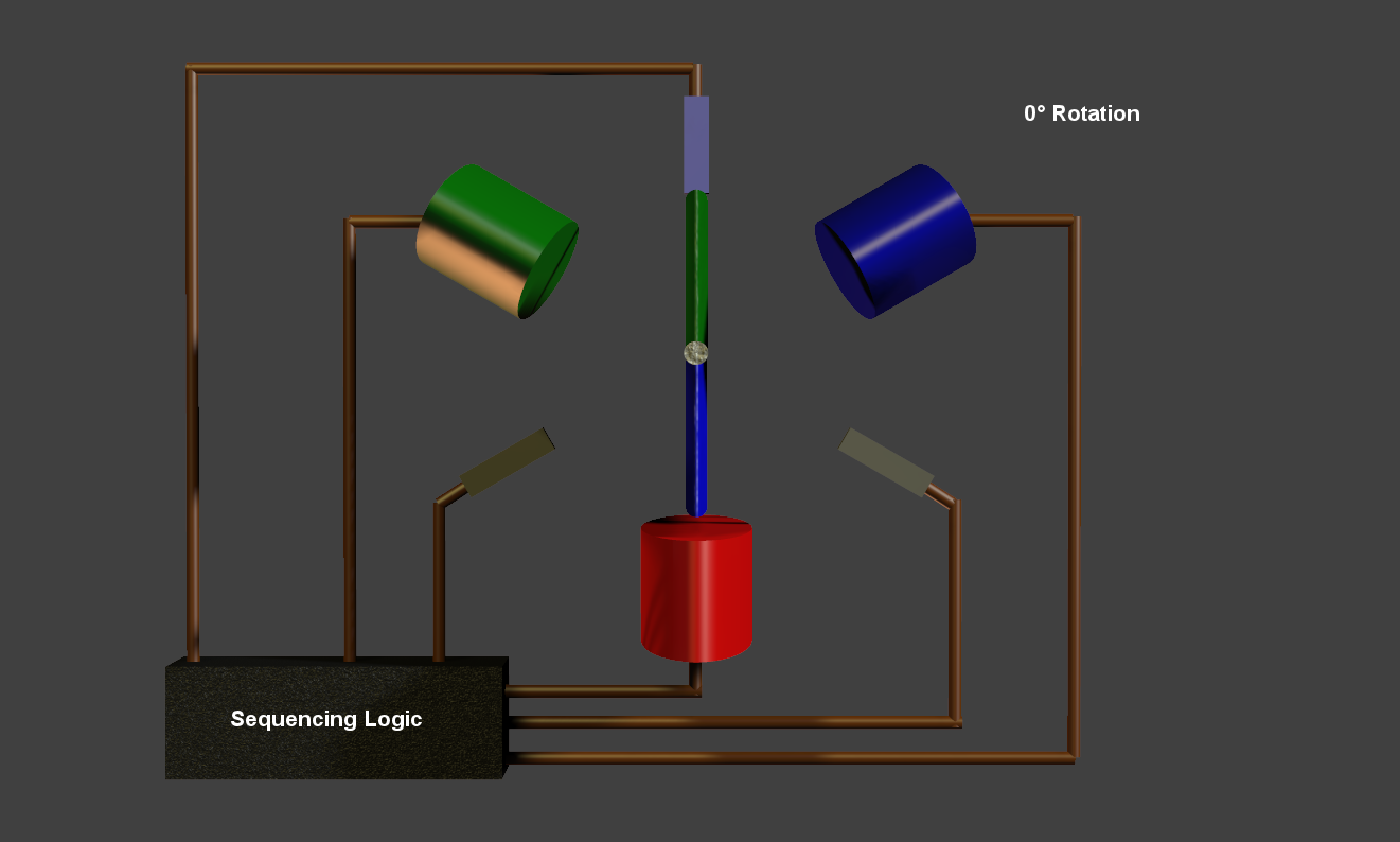
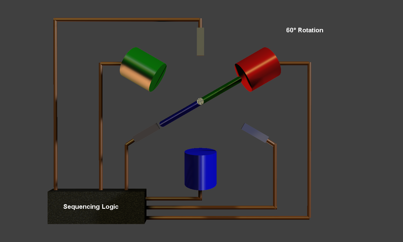
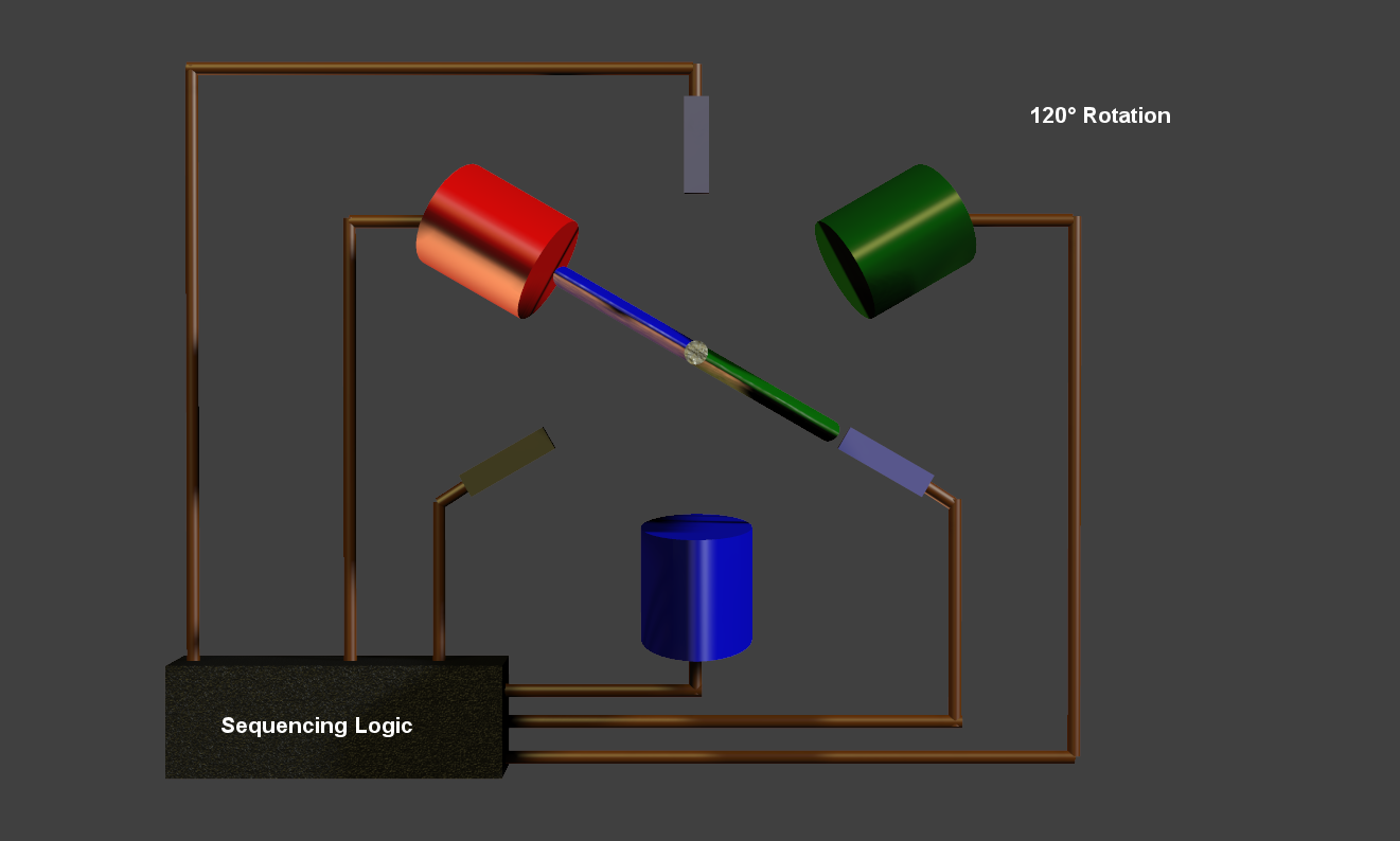
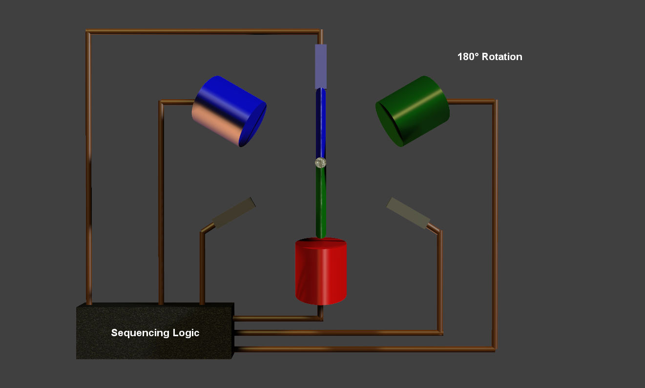
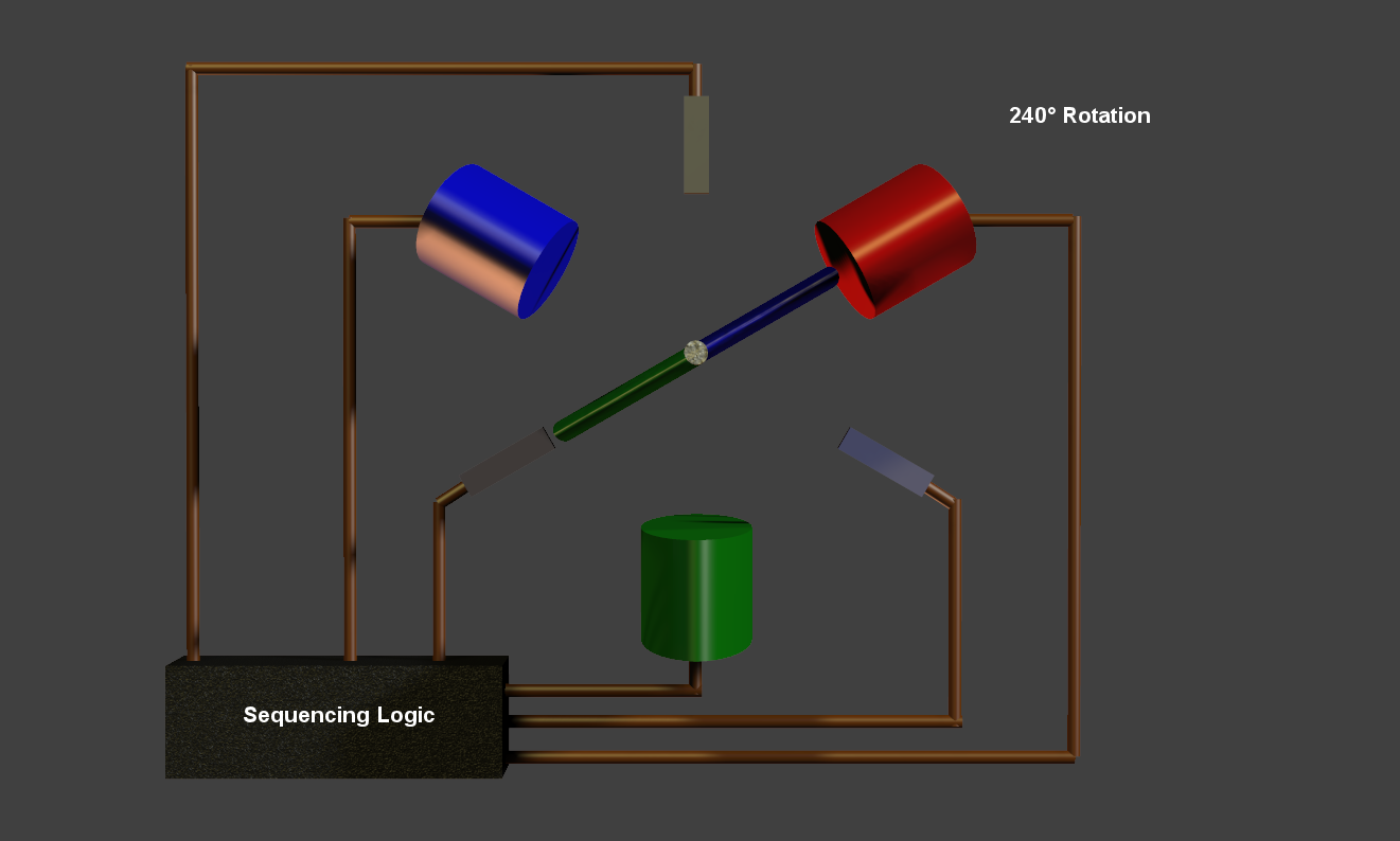
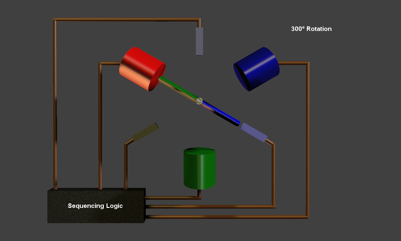
In these images you will notice that one field magnetic is always "off"; this is what allows the BLDC to enjoy it's higher efficiency...it literally uses 33% less energy than a brushed DC motor...nice "twist".
Now...at no time is there any true "AC" in this system, even IF it "looks" that way. The DC from the source is literally switched so that it flows to where it is needed. If we were to attempt to apply 3 phase AC to this system; it would, the worse case; melt down. In the best case; loose efficiency and output power (because of the nature of this system...the "third" phase would actually interfere with the systems operation).
Anyway that is what I did with these BLDC motors...just to insure I was right...and as usual I am.
Here is how a BLDC motor works:
First we'll start with a rudimentary controller, nothing extravagant, just the basics...
You should notice that only one "field bridge" is illustrated...within this bridge are a few logic elements, and, in our example, 5 MOSFET transistors. These transistors will act as switches for our high voltage, high current "drive" for our three field magnets.
The way this motor works is that the permanent magnet we used to see in our slot car motors has been moved fro the field to the armature, this way we have no need of brushed or current flow in the armature. Solves some issues, has others of its own; like the magnetic field around the armature now must rotate and "drag" the armature along. Doing this efficiently requires precise timing.
That timing is supplied by the "sequencing logic". This part would probably have a microprocessor in it to help with control and interface tasks.
The timing of this beast is quite important...
This is where we find it difficult to differentiate between AC and DC. We see our field magnets being driven with what appears to be square waves of some sort, and thus "AC". While under some circumstances, this kind of "switched" waveform may be thought of as "AC", this isn't one of those cases. The real differences that come into play here regarding the "AC" component will not become significant until much higher frequencies are attained, and in this application those frequencies are highly improbable; would indicate something broken).
Here is a series of images showing the state of the field magnets at each of the systems "switching" pints.
In these images you will notice that one field magnetic is always "off"; this is what allows the BLDC to enjoy it's higher efficiency...it literally uses 33% less energy than a brushed DC motor...nice "twist".
Now...at no time is there any true "AC" in this system, even IF it "looks" that way. The DC from the source is literally switched so that it flows to where it is needed. If we were to attempt to apply 3 phase AC to this system; it would, the worse case; melt down. In the best case; loose efficiency and output power (because of the nature of this system...the "third" phase would actually interfere with the systems operation).
a reply to: tanka418
Right, it was not clear what you meant by "switched-DC". I'm still not sure I would consider it DC but I think we can move on.
Usually motor controllers do not have that topology of a single-phase H-bridge per field winding. Usually automotive electric motors of any type are wye connected, so instead the drive they use will use a 3-phase H-bridge. You also connected the gate-drive to the body of the MOSFET instead of the gate. Not a big change from what you suggested since the field current currents stay the same.

Incidentally, this is the exact same topology as a 3-phase inverter.
Electric vehicles also require torque control - turning on transistors without modulation will result in massive inrush currents and no torque control. Hence PWM and some control technique is required. Here's an example. Hence what we really have is an inverter - identical to those required to drive a PMSM machine. Actually most motor controllers that can drive BLDC can also drive PMSM since they are so similar. The only difference is for PMSM instead of using hall effect sensors a more accurate encoder is needed and the modulation software is changed (the motor controller efficiency is probably going to be relatively similar between them).
In your terminology, do you not call a inverter an inverter if it's controlling a BLDC motor? I suppose a better term would be "motor controller" but the device ends up basically identical whether it's driving BLDC, IM, or PMSM. iirc, switched reluctance motors require a far different topology.
Just because a BLDC motor only (under this control strategy) has two-phases conducting at any given point in time, this does not actually mean it's more efficient. That's like saying a single-phase system is three times more efficient than a three-phase system.
In any case, here's a PMSM page with detailed efficiency data:
www.yasamotors.com...
Hence it is literally impossible for BLDC to require 33% less energy. Also note the cooling rate required. You could probably cool it with a PC-style water-cooling system if you wanted to.
And here's a study by MIT on Induction motor efficiency for electric vehicles:
Most EVs are PMSM not BLDC or IM. I suspect Tesla uses IM because they either have an innovative design or their car is in a totally different market to other EVs. It's a luxury sedan, not an econobox.
Control of electric motors is a very complicated topic, such blanket statements are not necessarily true:
ieeexplore.ieee.org...
I assume you have IEEE access, you can probably find the same study or similar by googling it.
I have provided PMSM motor controllers with >95% efficiency and PMSM with over 90% efficiency. I have also provided a experimental inverter with over 99% peak efficiency.
Right, it was not clear what you meant by "switched-DC". I'm still not sure I would consider it DC but I think we can move on.
Usually motor controllers do not have that topology of a single-phase H-bridge per field winding. Usually automotive electric motors of any type are wye connected, so instead the drive they use will use a 3-phase H-bridge. You also connected the gate-drive to the body of the MOSFET instead of the gate. Not a big change from what you suggested since the field current currents stay the same.
Incidentally, this is the exact same topology as a 3-phase inverter.
Electric vehicles also require torque control - turning on transistors without modulation will result in massive inrush currents and no torque control. Hence PWM and some control technique is required. Here's an example. Hence what we really have is an inverter - identical to those required to drive a PMSM machine. Actually most motor controllers that can drive BLDC can also drive PMSM since they are so similar. The only difference is for PMSM instead of using hall effect sensors a more accurate encoder is needed and the modulation software is changed (the motor controller efficiency is probably going to be relatively similar between them).
In your terminology, do you not call a inverter an inverter if it's controlling a BLDC motor? I suppose a better term would be "motor controller" but the device ends up basically identical whether it's driving BLDC, IM, or PMSM. iirc, switched reluctance motors require a far different topology.
In these images you will notice that one field magnetic is always "off"; this is what allows the BLDC to enjoy it's higher efficiency...it literally uses 33% less energy than a brushed DC motor...nice "twist".
Just because a BLDC motor only (under this control strategy) has two-phases conducting at any given point in time, this does not actually mean it's more efficient. That's like saying a single-phase system is three times more efficient than a three-phase system.
In any case, here's a PMSM page with detailed efficiency data:
www.yasamotors.com...
Hence it is literally impossible for BLDC to require 33% less energy. Also note the cooling rate required. You could probably cool it with a PC-style water-cooling system if you wanted to.
And here's a study by MIT on Induction motor efficiency for electric vehicles:
The induction motor presented here, designed with the fundamental requirement that it be able to deliver a peak power of 50 kW over a relatively narrow speed range, turns out to be nearly the same size as the permanent magnet motor designed for the same purpose. In application with a typical driving cycle, the induction machine turns out to be more efficient.
web.mit.edu...
Most EVs are PMSM not BLDC or IM. I suspect Tesla uses IM because they either have an innovative design or their car is in a totally different market to other EVs. It's a luxury sedan, not an econobox.
If we were to attempt to apply 3 phase AC to this system; it would, the worse case; melt down. In the best case; loose efficiency and output power (because of the nature of this system
Control of electric motors is a very complicated topic, such blanket statements are not necessarily true:
The experimental results show that it is advantageous to use non-sinusoidal current injection only in lower frequency range until drive conduction and stator resistive losses are higher than iron losses of the machine after which the algorithm can be modified to sinusoidal current injection thus maintaining higher efficiency operation.
ieeexplore.ieee.org...
I assume you have IEEE access, you can probably find the same study or similar by googling it.
I have provided PMSM motor controllers with >95% efficiency and PMSM with over 90% efficiency. I have also provided a experimental inverter with over 99% peak efficiency.
edit on 13/6/14 by C0bzz because: (no reason given)
a reply to: C0bzz
That MIT study is reassuring to me. There will be no need for large scale production of strategically insecure and polluting (at the mine) rare-earths in order to electrify transportation with permanent magnets. Improvements in intelligent motor controllers mean that induction motors can be well optimized for any operating point.
Of course there are always needs for permanent magnets but there won't be any enormous demand.
We'll need a bunch of copper, but copper for this use will be a small fraction of current use---construction (plumbing) is the biggest consumer.
new topics
-
Weinstein's conviction overturned
Mainstream News: 54 seconds ago -
Supreme Court Oral Arguments 4.25.2024 - Are PRESIDENTS IMMUNE From Later Being Prosecuted.
Above Politics: 1 hours ago -
Krystalnacht on today's most elite Universities?
Social Issues and Civil Unrest: 1 hours ago -
Chris Christie Wishes Death Upon Trump and Ramaswamy
Politicians & People: 2 hours ago -
University of Texas Instantly Shuts Down Anti Israel Protests
Education and Media: 4 hours ago -
Any one suspicious of fever promotions events, major investor Goldman Sachs card only.
The Gray Area: 6 hours ago -
God's Righteousness is Greater than Our Wrath
Religion, Faith, And Theology: 10 hours ago
top topics
-
VP's Secret Service agent brawls with other agents at Andrews
Mainstream News: 15 hours ago, 11 flags -
Nearly 70% Of Americans Want Talks To End War In Ukraine
Political Issues: 16 hours ago, 6 flags -
Sunak spinning the sickness figures
Other Current Events: 15 hours ago, 5 flags -
Electrical tricks for saving money
Education and Media: 13 hours ago, 4 flags -
Supreme Court Oral Arguments 4.25.2024 - Are PRESIDENTS IMMUNE From Later Being Prosecuted.
Above Politics: 1 hours ago, 4 flags -
Krystalnacht on today's most elite Universities?
Social Issues and Civil Unrest: 1 hours ago, 4 flags -
University of Texas Instantly Shuts Down Anti Israel Protests
Education and Media: 4 hours ago, 2 flags -
Any one suspicious of fever promotions events, major investor Goldman Sachs card only.
The Gray Area: 6 hours ago, 2 flags -
Chris Christie Wishes Death Upon Trump and Ramaswamy
Politicians & People: 2 hours ago, 1 flags -
God's Righteousness is Greater than Our Wrath
Religion, Faith, And Theology: 10 hours ago, 1 flags
active topics
-
Weinstein's conviction overturned
Mainstream News • 0 • : 5thHead -
Supreme Court Oral Arguments 4.25.2024 - Are PRESIDENTS IMMUNE From Later Being Prosecuted.
Above Politics • 6 • : TzarChasm -
University of Texas Instantly Shuts Down Anti Israel Protests
Education and Media • 92 • : FlyersFan -
President BIDEN Vows to Make Americans Pay More Federal Taxes in 2025 - Political Suicide.
2024 Elections • 143 • : SchrodingersRat -
SETI chief says US has no evidence for alien technology. 'And we never have'
Aliens and UFOs • 65 • : andy06shake -
Sunak spinning the sickness figures
Other Current Events • 18 • : andy06shake -
British TV Presenter Refuses To Use Guest's Preferred Pronouns
Education and Media • 155 • : Annee -
Nearly 70% Of Americans Want Talks To End War In Ukraine
Political Issues • 76 • : FlyersFan -
The Reality of the Laser
Military Projects • 49 • : 5thHead -
Chris Christie Wishes Death Upon Trump and Ramaswamy
Politicians & People • 6 • : mysterioustranger